
Cutter fixing structure and cutter and cutter handle suitable for same

A fixed structure and cutting tool technology, applied in the field of machining cutting tools, can solve the problems of scrapped parts and affecting the machining accuracy of cutting tools, and achieve the effect of easy disassembly and assembly

Active Publication Date: 2016-04-20
CENTRIX EG
View PDF7 Cites 7 Cited by
  • Summary
  • Abstract
  • Description
  • Claims
  • Application Information

AI Technical Summary

Problems solved by technology

Even a small amount of axial movement of the tool will affect the machining accuracy of the tool, and even cause parts to be scrapped

Method used


Image

  • Cutter fixing structure and cutter and cutter handle suitable for same
  • Cutter fixing structure and cutter and cutter handle suitable for same
  • Cutter fixing structure and cutter and cutter handle suitable for same

Examples


Embodiment Construction

[0020] The present invention will be further described below in conjunction with the accompanying drawings and specific embodiments.

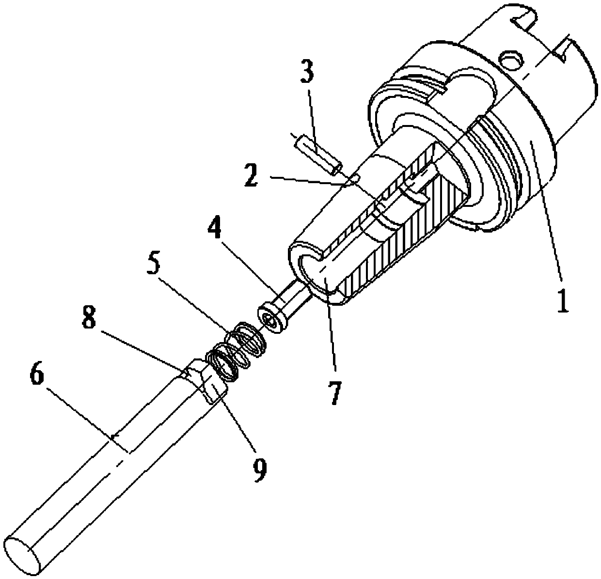
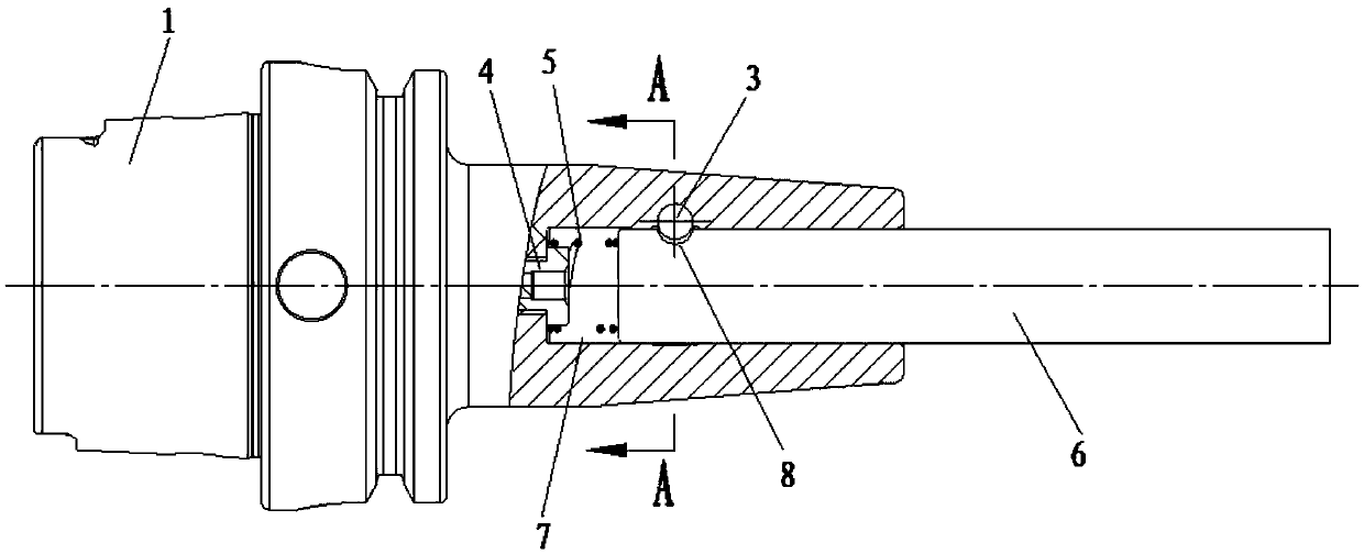
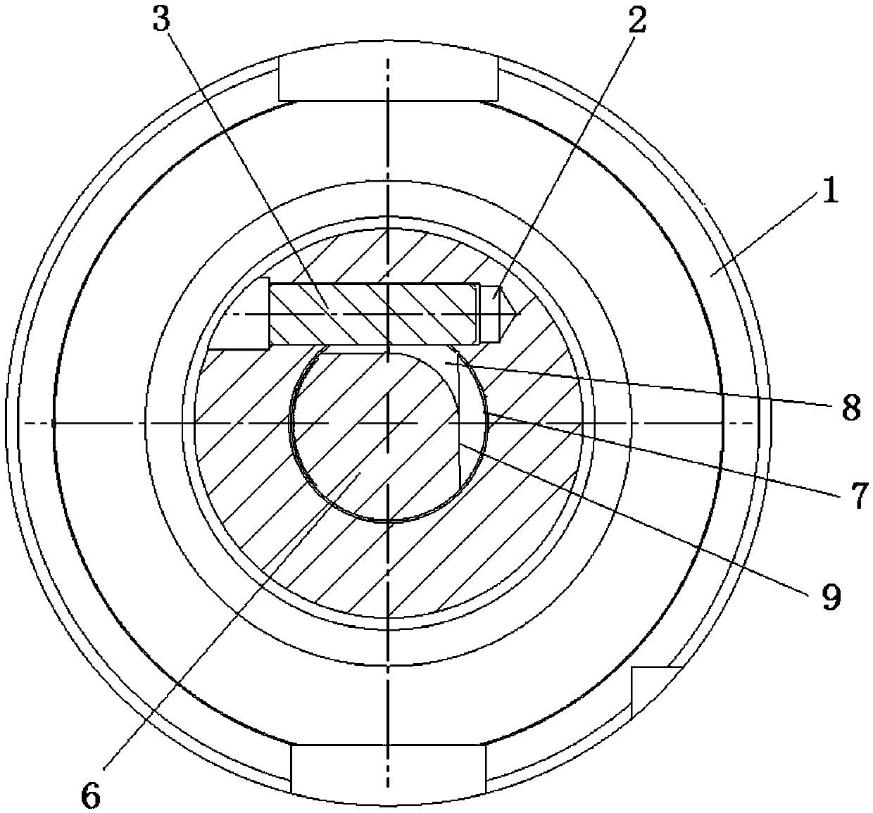
[0021] The knife fixing structure includes a knife handle 1 and a knife 6. The knife handle 1 is provided with a knife hole 7 extending inward from the end of the knife handle 1, the knife 6 is inserted into the knife hole 7, and the knife handle 1 holds the knife 6; it also includes a safety lock Pin 3; the handle 1 is provided with a lock pin hole 2 extending inward from the side of the handle 1; the cutter 6 is provided with a lock pin passage groove 8 and a knife retraction concave platform 9, and the knife retraction concave platform 9 is formed by the end surface of the cutter 6 Extend to the lock pin through the slot 8; the safety lock pin 3 is loaded into the lock pin hole 2 and inserted into the lock pin through the slot 8, the safety lock pin 3 restricts the axial movement of the tool 6; the handle 1 releases the clamping of the tool 6...


PUM


Abstract

The invention discloses a cutter fixing structure and a cutter and a cutter handle suitable for the same, relates to the field of machining tools, and provides a cutter fixing structure capable of preventing the cutter from moving. The cutter fixing structure comprises the cutter handle and the cutter, a cutter hole extending from the end of the cutter handle to the inside is formed in the cutter handle, and the cutter is inserted into the cutter hole and clamped by the cutter handle. The cutter fixing structure further comprises a safety locking pin, a locking pin hole extending from the side of the cutter handle to the inside is formed in the cutter handle, the cutter is provided with a locking pin passing groove and a retracting concave platform, the retracting concave platform extends from the end face of the cutter to the locking pin passing groove, and the safety locking pin is installed in the locking pin hole and inserted into the locking pin passing groove and is used for limiting axial movement of the cutter; when clamping on the cutter is released by the cutter handle, and the cutter is rotated till the retracting concave platform is over against the safety locking pin, the cutter moves out of the cutter handle without limitation of the safety locking pin. The cutter fixing structure is mainly suitable for shrinkage fit of the cutter handle.

Description

technical field [0001] The invention relates to the field of machining tools, in particular to a tool fixing structure and a tool and a tool holder suitable for the tool fixing structure. Background technique [0002] Shrink-fit tool holders are widely used in tool holders, and tool holes are provided in the tool holders. When clamping the tool, the tool handle is heated to expand the tool hole, and then the tool is inserted into the tool hole. After the tool handle cools down, the tool hole shrinks and the tool is clamped. Usually, shrink-fit holders can hold the tool stably and avoid axial movement of the tool. However, in some special cases, the axial movement of the tool will occur. For example, after the tool has been processed for a long time, there will be a small amount of axial movement of the tool, and the main movement of the tool is outward. Even a small amount of axial movement of the tool will affect the machining accuracy of the tool, and even cause parts to...

Claims


Application Information

Patent Timeline
IPC IPC(8): B23Q3/12
CPCB23Q3/12
Inventor 张敬志高嵩杨华军赵庆军
Owner CENTRIX EG
Learn More