

A clamping linkage mechanism and claw plate
A linkage mechanism and clamping technology, applied in the direction of workpiece clamping devices, manufacturing tools, etc., can solve the problems of time-consuming and labor-intensive clamping claws, high cost, and low work efficiency, and achieve simple and ingenious structure, high work efficiency, and low cost Effect
- Summary
- Abstract
- Description
- Claims
- Application Information
AI Technical Summary
Problems solved by technology
Method used
Image

Examples
Embodiment Construction
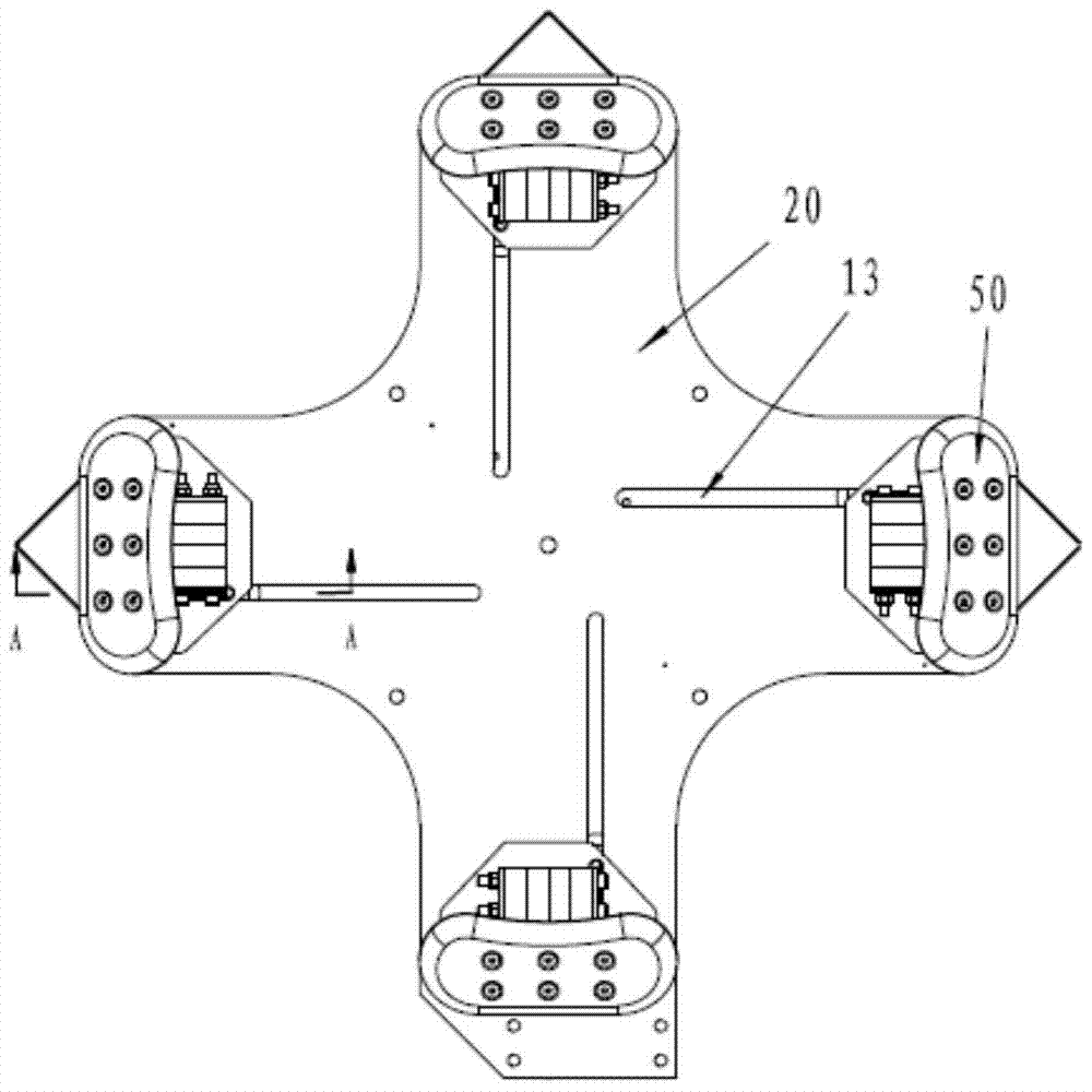
[0031] In order to realize the synchronous adjustment of the clamping jaws of the jaw plate, the traditional solution is that each clamping jaw is equipped with a power mechanism, which can be adjusted one by one or simultaneously to meet the clamping requirements. However, the cost of the claw plate mechanism equipped with multiple powers is relatively high, and the volume is relatively large. Moreover, during operation, it is time-consuming and labor-intensive to adjust the clamping claws individually, and the work efficiency is low. Moreover, due to the existence of errors, even if multiple power mechanisms are adjusted at the same time, the accuracy of the position of the clamping claws cannot be guaranteed, and the precision is not high.
[0032] Aiming at the deficiencies in the prior art, the present invention provides a clamping linkage mechanism and claw plate, so that the whole mechanism only needs a single power to drive a single clamping claw, and realizes multiple ...
PUM
 Abstract
Description
Claims
Application Information