AI technical title is built by PatSnap AI team. It summarizes the technical point description of the patent document.
A punching machine, a new type of technology, applied in the direction of punching machines, presses, manufacturing tools, etc., can solve problems that limit the development of punching machines, and achieve the effects of helping to maintain strength, prolong equipment life, and eliminate unbalanced forces
Active Publication Date: 2017-10-13
MINGXUDONGGUAN PRECISION MACHINARY CO LTD
View PDF8 Cites 0 Cited by
Summary
Abstract
Description
Claims
Application Information
AI Technical Summary
This helps you quickly interpret patents by identifying the three key elements:
Problems solved by technology
Method used
Benefits of technology
Problems solved by technology
[0006] There are some defects in the above three kinds of punching machines, which limit the development of punching machines, and there is a need for improvement
Method used
Image
Click on the blue label to locate the original text in one second.
Reading with bidirectional positioning of images and text.
Examples
Embodiment Construction
[0030] The present invention will be further described below in conjunction with the accompanying drawings and embodiments, which are preferred embodiments of the present invention.
[0031] Example.
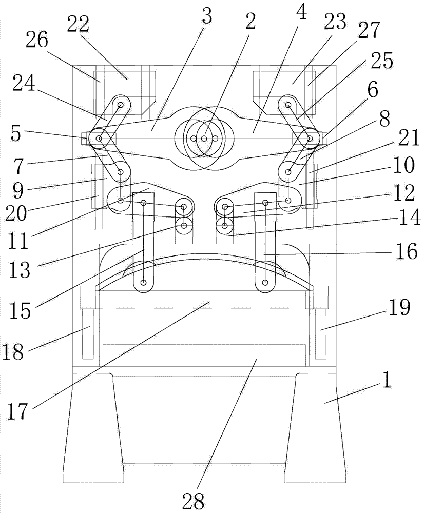
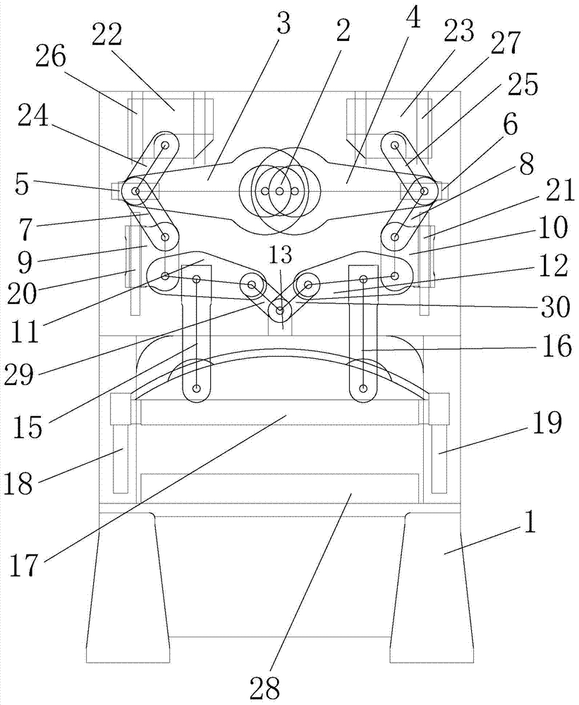
[0032] Such as figure 1 with figure 2As shown, a novel punch press of the present invention includes a frame 1, a driving device, a crankshaft 2, a first crankshaft connecting rod 3, a second crankshaft connecting rod 4, a first horizontal guide block 5, a second horizontal guide block 6, The first transfer link 7, the second transfer link 8, the first vertical guide link 9, the second vertical guide link 10, the first lever 11, the second lever 12, the first mold adjusting connecting plate 29, The second mold adjusting connecting plate 30, the first slider connecting rod 15, the second slider connecting rod 16, the slider 17 and the workbench 28, the driving device and the workbench 28 are respectively fixed with the frame 1 connected, the first horizontal guide block 5 and...
PUM
Abstract
The invention relates to a new type of punching machine, which includes a frame, a driving device, a crankshaft, a first crankshaft connecting rod, a second crankshaft connecting rod, a first horizontal guide block, a second horizontal guide block, a first connecting rod, a second Transfer link, the first vertical guide link, the second vertical guide link, the first lever, the second lever, the first mold adjusting connecting plate, the second adjusting mold connecting plate, the first slider connecting rod, the second Slider connecting rod, slider and worktable, the driving device drives and connects the crankshaft, and the crankshaft drives and connects the first crankshaft connecting rod and the second crankshaft respectively, and the slider is located at the working table. Above the table; the new punching machine has simple structure, small inertia, high precision, long dwell time at the bottom dead center, smooth stamping surface of the stamped workpiece, improves the quality of the stamped workpiece, receives small reverse impact force, and has little wear on the equipment. The service life of the equipment is extended.
Description
technical field [0001] The invention relates to the technical field of mechanical equipment, in particular to a novel punching machine. Background technique [0002] A punch press is a device used to stamp sheets. Existing punch presses include the following three categories: 1. crankshaft punch presses; 2. toggle punch presses; 3. multi-link punch presses. [0003] The crankshaft punch is easy to manufacture and low in cost. During the high-speed stamping process, the stamping die has a large inertia, the depth of stamping will change with the speed, and the precision is not easy to control. The time from the time of the workpiece to the stamping of the die to the set depth of the workpiece or the time from the point where the stamping force occurs to the end point of stamping) is short, resulting in poor metal fluidity of the workpiece to be processed, and it is easy to make the stamping surface rough. The quality of the stamping parts in the stamping process is poor. Th...
Claims
Application Information
Patent Timeline
Application Date:The date an application was filed.
Publication Date:The date a patent or application was officially published.
First Publication Date:The earliest publication date of a patent with the same application number.
Issue Date:Publication date of the patent grant document.
PCT Entry Date:The Entry date of PCT National Phase.
Estimated Expiry Date:The statutory expiry date of a patent right according to the Patent Law, and it is the longest term of protection that the patent right can achieve without the termination of the patent right due to other reasons(Term extension factor has been taken into account ).
Invalid Date:Actual expiry date is based on effective date or publication date of legal transaction data of invalid patent.

