Cold heading machining equipment

A processing equipment and cold heading technology, applied in the field of cold heading processing equipment, can solve problems such as difficult to meet production needs, low contact forming efficiency, etc., and achieve high production efficiency

Inactive Publication Date: 2022-03-25
DONGGUAN HUANO ALLOY
View PDF6 Cites 0 Cited by
  • Summary
  • Abstract
  • Description
  • Claims
  • Application Information

AI Technical Summary

Problems solved by technology

[0004] In view of the above-mentioned related technologies, the inventor believes that the method of cold heading machine in the related technologies to form the contacts is inefficient and difficult to meet the needs of production

Method used


Image

  • Cold heading machining equipment
  • Cold heading machining equipment
  • Cold heading machining equipment

Examples


Embodiment 1

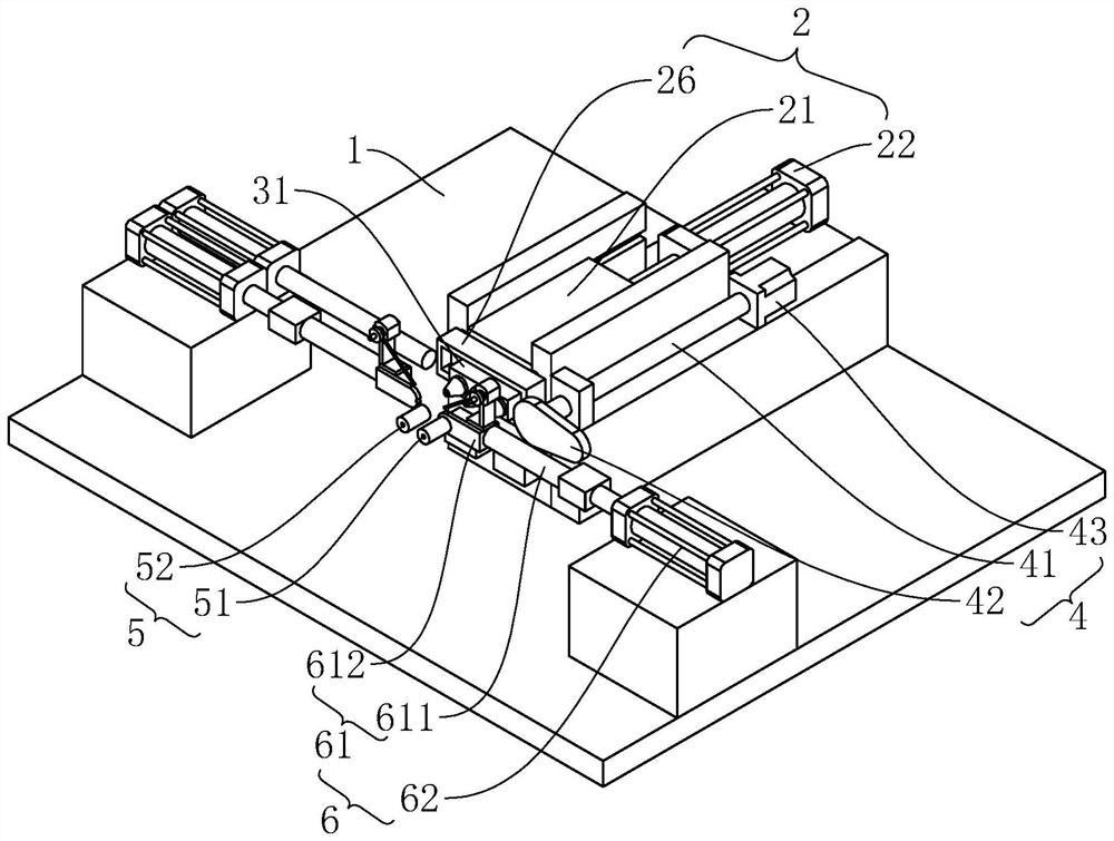
[0048] refer to figure 1 , a cold heading processing equipment, including a frame 1, the role of the frame 1 is to carry the following parts or provide a bearing body, so the shape and structure of the frame 1 are not limited.

[0049] refer to figure 1 The frame 1 is provided with an upsetting power mechanism 2. The upsetting power mechanism 2 includes a mounting block 21 and a telescopic cylinder 22. The mounting block 21 slides and fits on the frame body along the first direction. In this embodiment, the first direction It is a horizontal direction. In other embodiments of the present application, the first direction may be a near-horizontal direction, and the near-horizontal direction is any direction with an angle less than 15° with the horizontal direction. The telescopic cylinder 22 is fixedly installed on the frame body, and the piston rod of the telescopic cylinder 22 is arranged along the first direction, and the mounting block 21 is fixedly connected to the end of ...

Embodiment 2

[0058] refer to Figure 4 , The difference between this embodiment and Embodiment 1 is that the upsetting power mechanism 2 is different.

[0059] In this embodiment, the upsetting power mechanism 2 includes a mounting block 21 , a driving member 23 , a driving arm 24 and a crankshaft 25 . The mounting block 21 is slidably disposed on the frame 1 along a first direction. A sliding slot for guiding the mounting block 21 is opened on the frame 1, and the mounting block 21 is accommodated in the sliding slot and is slidingly connected with the groove wall of the sliding slot. The crankshaft 25 is arranged in the vertical direction, the connecting rod journal of the crankshaft 25 is perpendicular to the first direction, the crankshaft 25 is carried on the frame 1 and is connected with the bearing of the frame 1; In the embodiment, the driving member 23 is set as a servo motor, the rotation speed of the servo motor is controllable, and the output shaft of the servo motor is coaxi...

Embodiment 3

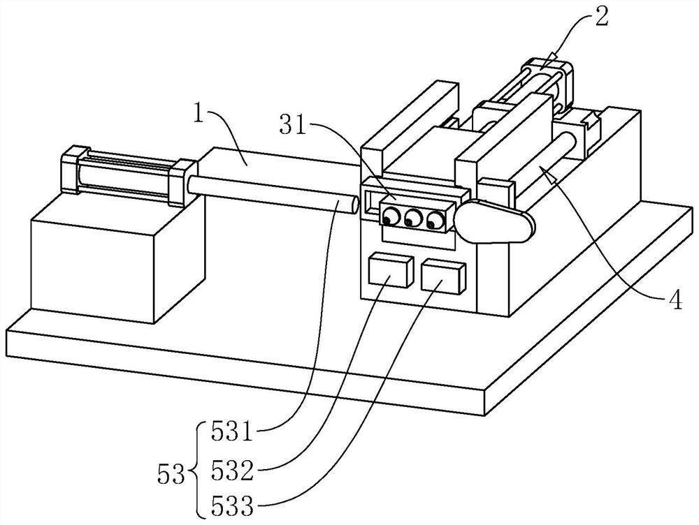
[0062] refer to Figure 5 , The difference between this embodiment and Embodiment 1 is that the punch module 3, the mold module 5 and the mold changing power mechanism 4 are different.

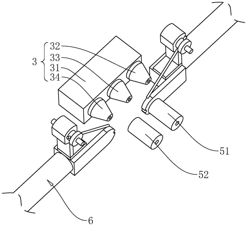
[0063] In this embodiment, the side of the mounting block 21 away from the telescopic cylinder 22 is provided with a chute 26 extending in the vertical direction, and the chute 26 is provided with a fixed block 31 slidably connected to the chute 26, and the fixed block 31 is connected to the chute 26 The cross sections of the sliding grooves are all T-shaped to ensure the stability of the fixed part when sliding in the sliding grooves. The side of the fixed block 31 away from the chute 26 is fixedly connected with the pre-upsetting punch 32 , the rough heading punch 33 and the finishing punch 34 at equal intervals along the vertical direction.

[0064] The mold changing power mechanism 4 includes a lifting motor 44 and a lifting screw rod 45. The lifting screw rod 45 is connected with the chu...


PUM


Abstract

The invention relates to the technical field of cold heading, in particular to cold heading machining equipment which is characterized in that the cold heading machining equipment comprises a rack and further comprises a punch module, the punch module comprises a fixing block, and a pre-heading punch, a rough heading punch and a fine heading punch are sequentially arranged on the fixing block; the mold module is arranged on the machine frame, and the mold module comprises a first mold and a second mold; the upsetting and pressing power mechanism is arranged on the machine frame, and the upsetting and pressing power mechanism is used for achieving the upsetting and pressing action; the die changing power mechanism is used for realizing a die changing action; and the feeding mechanism is arranged on the machine frame, and the feeding mechanism is used for conveying the upset material and the substrate to the position of a mold. The contact machining device has the effect of improving the contact machining efficiency of the cold heading machining device.

Description

technical field [0001] The present application relates to the technical field of cold heading, in particular to a cold heading processing equipment. Background technique [0002] The contact is a component widely used in the switch structure of electrical equipment. A contact consists of a base material and a conductive layer, which is usually assembled to the base material using a cold heading machine. [0003] In the related technology, the cold heading machine mainly includes a frame, a mounting block, a punch module, a mold, an active mechanism and a first driven mechanism, the mounting block is horizontally slid on the frame, and the punch module is vertically slidable on the The installation block, the punch module is equipped with pre-upsetting punch, rough heading punch and fine heading punch, and the mold is set on the frame. During the sliding process of the punch module, the mold can be respectively connected with the pre-upsetting punch, The rough heading punch...

Claims


Application Information

Patent Timeline
Patent Type & Authority Applications(China)
IPC IPC(8): B21J9/18B21J9/02B21J13/00B21J13/03B21K27/06
CPCB21J9/18B21J9/02B21J13/00B21J13/03B21K27/06
Inventor 蒋廷顺马鹏飞
Owner DONGGUAN HUANO ALLOY
Why Eureka
Try Eureka