Object measuring apparatus, object measuring method, and program product

a technology of object measurement and object, applied in the field of object measurement apparatus, can solve the problems of erroneously counting the number of passages of moving objects, heavy processing load, long calculation time, etc., and achieve the effect of accurately counting the number of a plurality of objects and high process speed

Inactive Publication Date: 2007-05-22
KONICA MINOLTA INC
View PDF1 Cites 76 Cited by
  • Summary
  • Abstract
  • Description
  • Claims
  • Application Information

AI Technical Summary

Benefits of technology

[0011]The present invention aims to provide an object measuring system capable of performing high speed process and accurately counting the number of a plurality of objects even in the case where the plurality of objects pass a boundary line simultaneously.
[0013]According to the object measuring system, it is sufficient to obtain motion vectors on a boundary line; therefore, it is unnecessary to calculate an optical flow with respect to a wide two-dimensional region. Accordingly, processing load can be lessened and higher processing speed can be achieved. At least one integral value is obtained by integrating components perpendicular to the boundary line of the motion vector with respect to one of positive and negative signs and the number of moving objects is calculated on the basis of the integral value. Consequently, even in the case where a plurality of moving objects pass the boundary line in opposite directions at the same time, erroneous counting can be prevented and the number of passing objects can be measured accurately. As described above, the number of moving objects passing the boundary line can be calculated accurately at high speed.
[0015]According to the object measuring system, it is sufficient to obtain motion vectors on a boundary line; therefore, it is unnecessary to calculate an optical flow with respect to a wide two-dimensional region. Accordingly, processing load can be lessened and higher processing speed can be achieved. Further, since the number of moving objects passing the boundary line is obtained on the basis of an integral value derived by integrating components perpendicular to the boundary line of the motion vector and a reference value regarding the integral value, even in the case where a plurality of moving objects pass the boundary line at the same time, erroneous counting can be prevented and the number of passing objects can be measured accurately.

Problems solved by technology

It causes problems of a heavy processing load and long calculation time.
However, the technique of Patent Document 1 (second conventional art) has a problem in that the number of passages of moving objects is erroneously counted in the case where a plurality of moving objects pass a boundary line simultaneously.

Method used


Image

  • Object measuring apparatus, object measuring method, and program product
  • Object measuring apparatus, object measuring method, and program product
  • Object measuring apparatus, object measuring method, and program product

Examples


Embodiment Construction

[0034]Hereinafter, embodiments of the present invention will be described with reference to the drawings.

Configuration

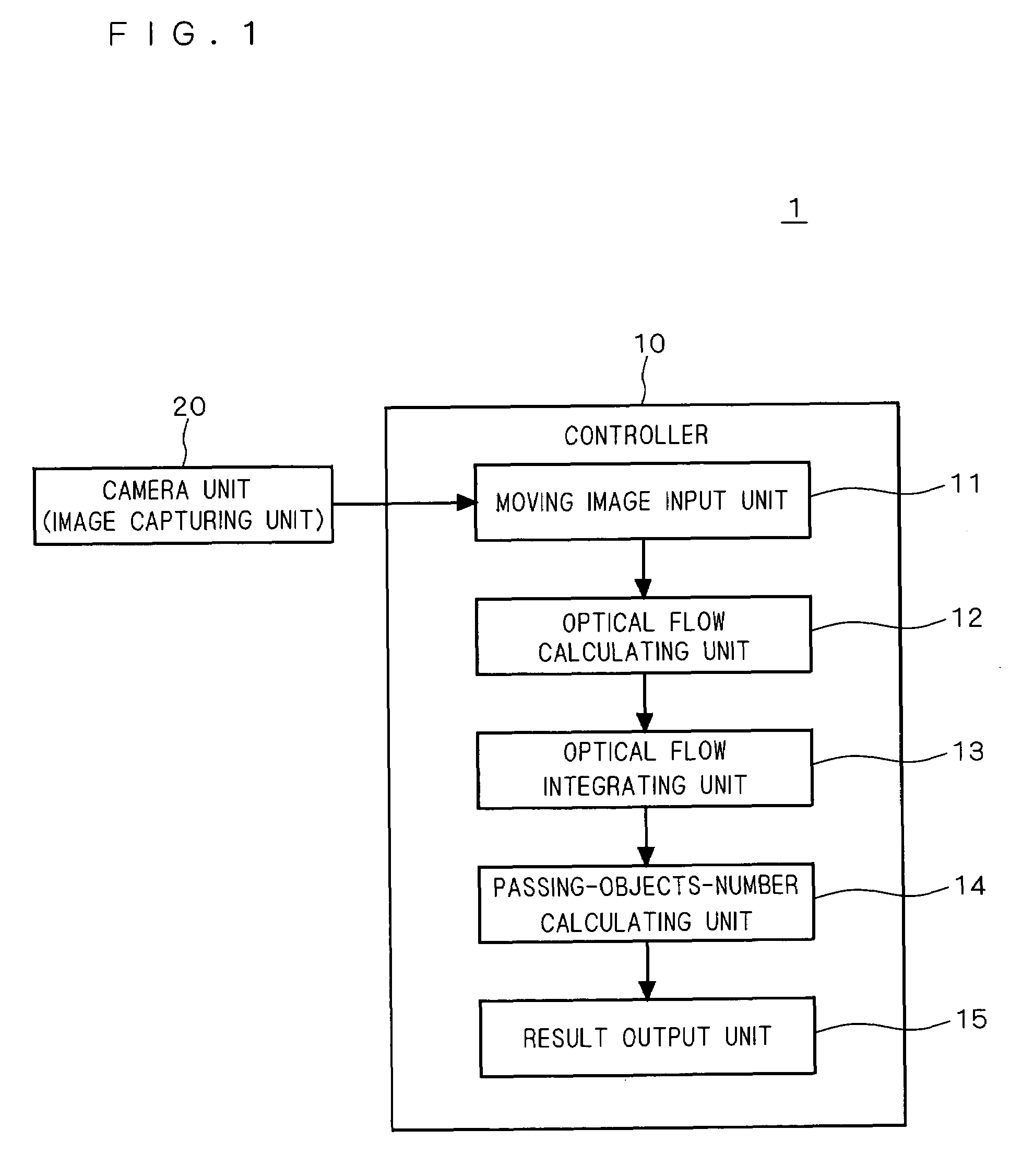
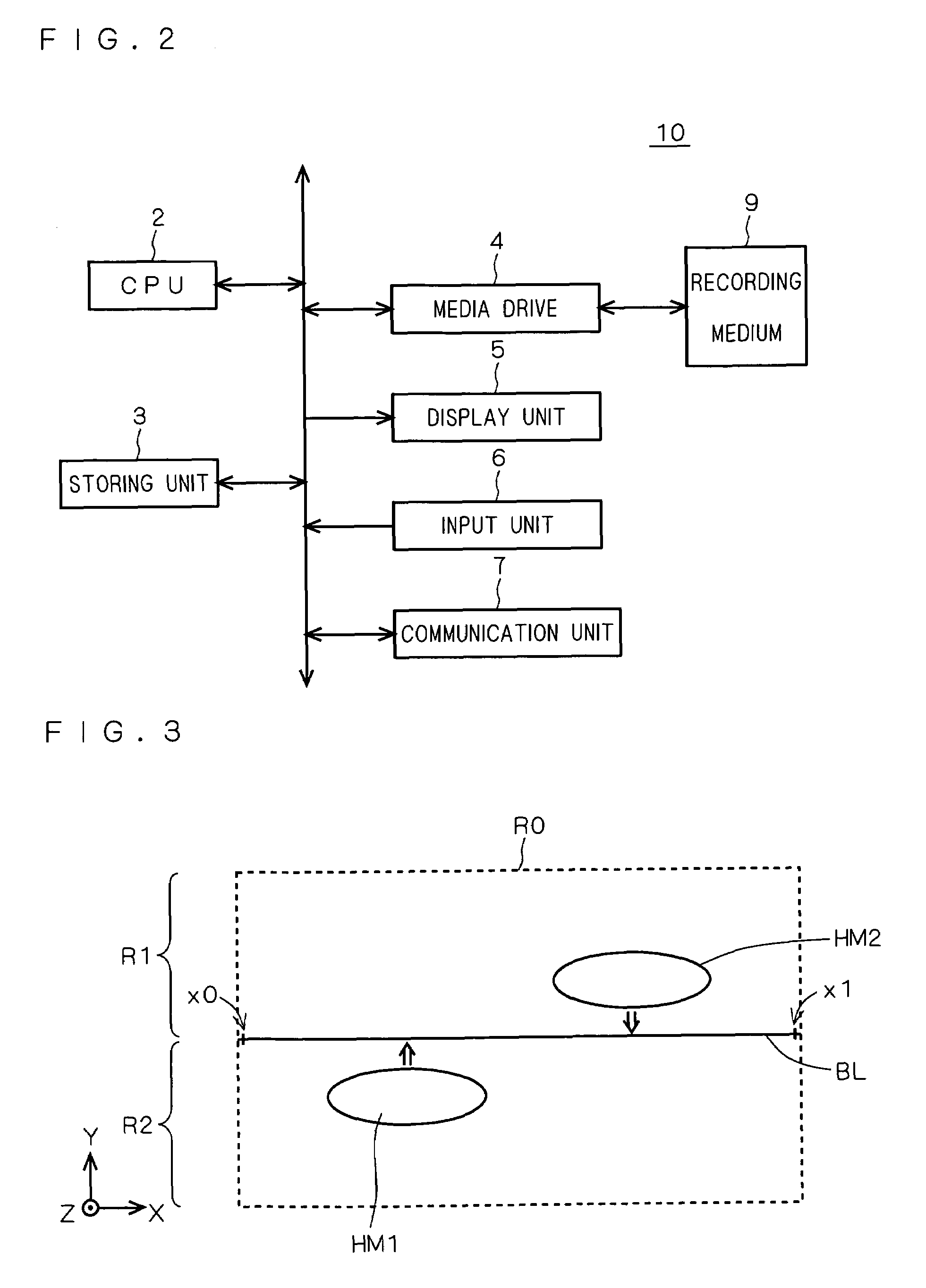
[0035]FIG. 1 is a diagram showing an object measuring apparatus 1 according to an embodiment of the present invention. As shown in FIG. 1, the object measuring apparatus 1 comprises a controller 10 and a camera unit (image capturing unit) 20. A case is assumed herein that the camera unit 20 is disposed on the ceiling of a predetermined position (e.g., a path, an entrance, an exit or the like) in a shop to grasp a moving state of a human.

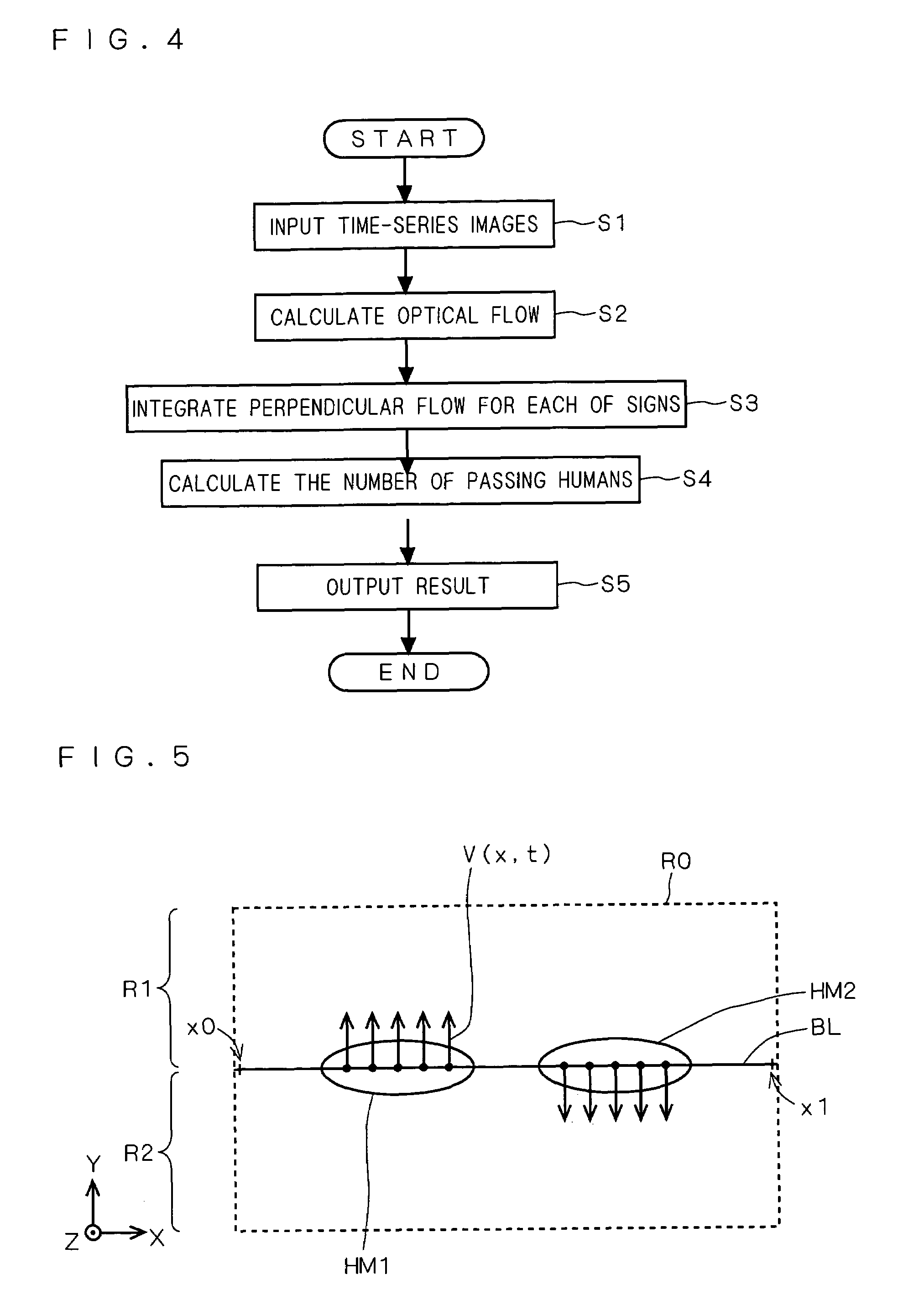
[0036]The camera unit 20 is disposed so that the optical axis of a lens of the camera unit 20 is parallel with a vertical direction (direction perpendicular to the floor face), and captures an image including a virtual boundary line BL (see FIG. 3 and the like) which divides a region into a first region R1 and a second region R2 in the shop. The object measuring apparatus 1 obtains the number of moving objects (humans) passing the bou...


PUM


Abstract

The present invention provides an object measuring apparatus capable of performing high-speed process and accurately counting the number of a plurality of objects even in the case where the plurality of objects pass a boundary line simultaneously. The object measuring apparatus extracts motion vectors at a plurality of times in each of a plurality of positions on a boundary line on the basis of a plurality of images. The object measuring apparatus obtains at least one integral value by integrating components perpendicular to the boundary line of the motion vectors. As the at least one integral value, for example, an integral value derived by integrating the perpendicular components of one of positive and negative signs is obtained. The object measuring apparatus calculates the number of moving objects (people and the like) passing the boundary line on the basis of the integral value.

Description

[0001]This application is based on application No. 2003-360580 filed in Japan, the contents of which are hereby incorporated by reference.BACKGROUND OF THE INVENTION[0002]1. Field of the Invention[0003]The present invention relates to an object measuring apparatus for performing a process of counting the number of moving objects, and techniques related thereto.[0004]2. Description of the Background Art[0005]There are techniques of using an optical flow in order to measure movement of a moving object (for example, see “Tracking a Person with 3-D Motion by Integrating Optical Flow and Depth”, by R. Okada, Y. Shirai, and J. Miura, Proc. 4th Int. Conf. on Automatic Face and Gesture Recognition, pp. 336-341, March, 2000 (Non-Patent Document 1) and Japanese Patent Application Laid-Open No. 2002-8018 (Patent Document 1)). The optical flow denotes a “vector field” constructed by “motion vectors” of corresponding pixels in two images.[0006]In such techniques, a camera is located at a predete...

Claims


Application Information

Patent Timeline
Patent Type & Authority Patents(United States)
IPC IPC(8): G06K9/03H04N9/24G02B9/02G06T1/00G06K9/00G06M11/00G06T7/20G06T7/60G07C9/00
CPCG06M11/00G07C9/00
Inventor KAWAKAMI, YUICHINAKANO, YUUSUKE
Owner KONICA MINOLTA INC
Why Eureka
Try Eureka