
Adjusting the contrast of a digital image with an adaptive recursive filter

a technology of adaptive recursive filter and digital image, applied in image enhancement, television system, instruments, etc., can solve the problems of large boundaries, flat image appearance, and large rendering of scene content,

Inactive Publication Date: 2004-04-27
MONUMENT PEAK VENTURES LLC
View PDF13 Cites 76 Cited by
  • Summary
  • Abstract
  • Description
  • Claims
  • Application Information

AI Technical Summary

Benefits of technology

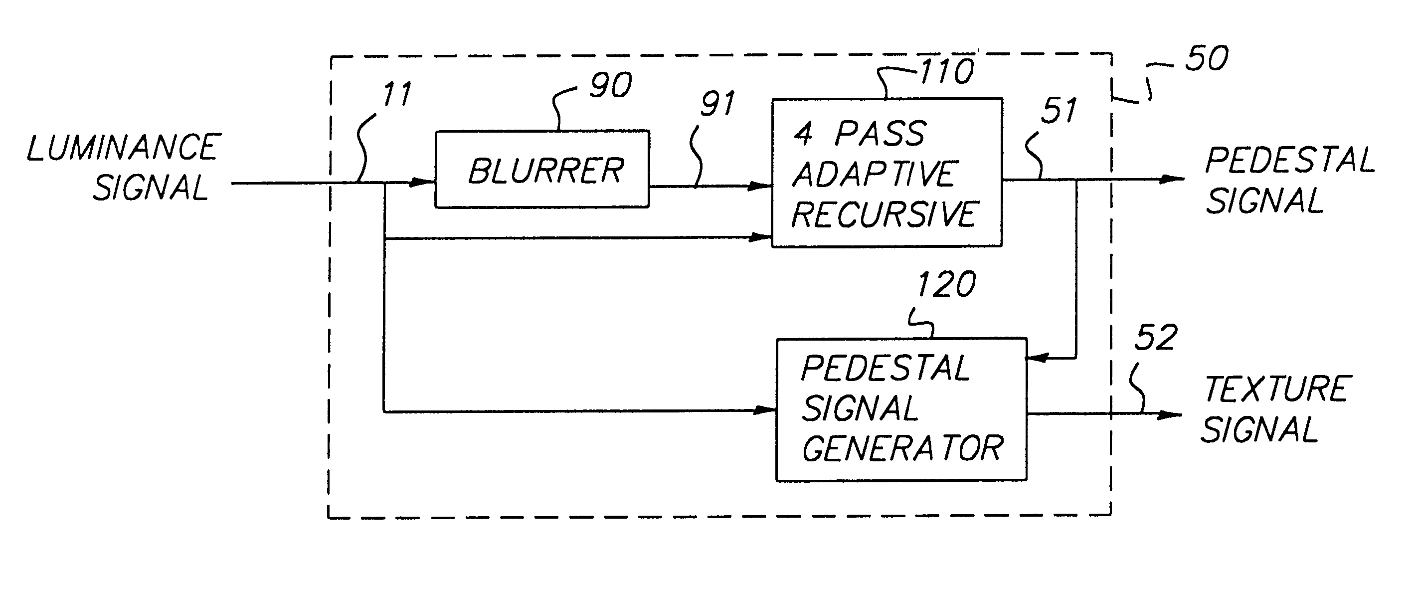
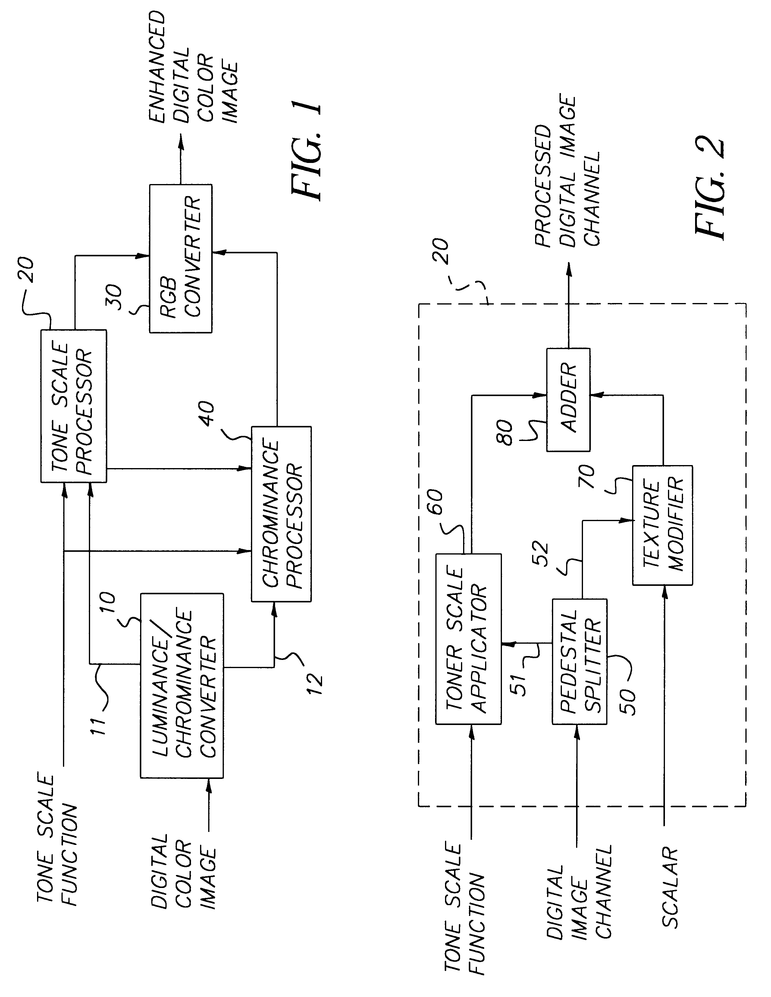
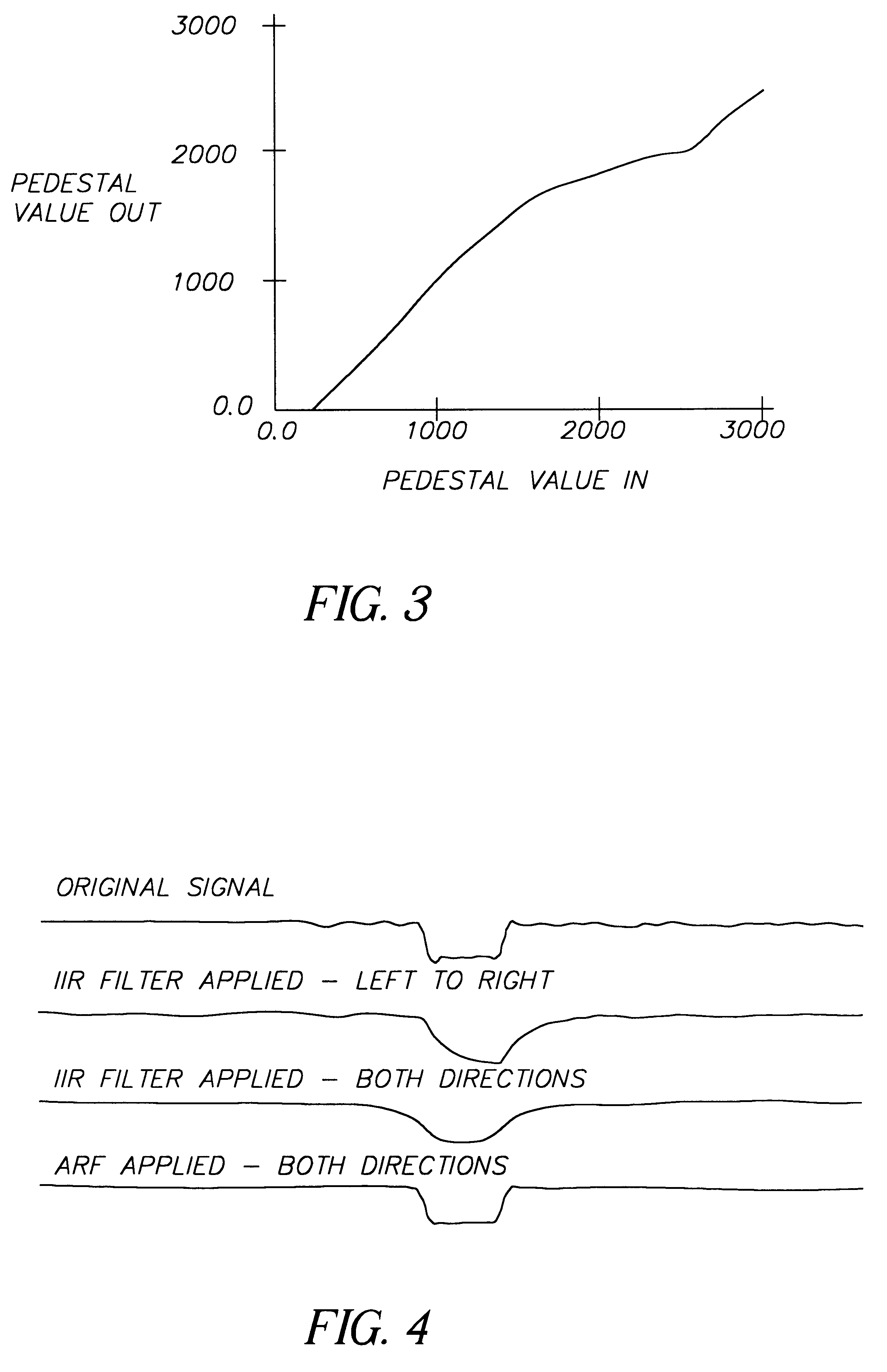
One advantage of the invention is that the tone scale function application process is relatively fast. Further, the image detail is preserved while the image macro-contrast is adjusted. In addition, the detail is preserved without reference to a specific detail size range (in contrast to most single linear filter approaches) and artifacts are prevented.The foregoing and other objects, aspects and advantages will be better understood from the following detailed description of a preferred embodiment of the invention with reference to the drawings, in which:FIG. 1 is a schematic architectural diagram of one embodiment of the invention;FIG. 2 is a schematic architectural diagram of one embodiment of the invention;FIG. 3 is a graph illustrating an example tone scale function;FIG. 4 shows example signal traces that illustrate the ARF;FIG. 5A is a graphical illustration of phase response of the IIR filter;FIG. 5B is a graphical illustration of the phase response of the forward and reverse filters;FIG. 6 is a schematic architectural diagram of the pedestal splitter;FIG. 7 is a schematic architectural diagram of the four-pass ARF;FIGS. 8A-D are arrangements of the ARF coefficients for the four two-dimensional single-pass ARFs;FIG. 9 is a planar illustration of the application of an ARF at a single position of a digital image channel;FIG. 10 is a graph illustrating the magnitude of the frequency response of the four-pass ARF (with the two-dimensional single-pass ARF), assuming that the filter coefficients remain constant;FIG. 11 is a schematic architectural diagram of the first signal-pass ARF with non-separable kernel;FIG. 12 is a graphical illustration of an example relationship between .DELTA..sub.min (i,j) and .alpha.;FIGS. 13A-D are arrangements of the ARF coefficients for the four separable single-pass ARFs;FIG. 14 is a graph illustrating the magnitude of the frequency response of the separable four-pass ARF, assuming that the filter coefficients remain constant;FIG. 15 is a schematic architectural diagram of the first signal-pass separable ARF;FIG. 16 is a schematic architectural diagram of an alternative pedestal splitter;FIG. 17 is a schematic architectural diagram of another alternative pedestal splitter; andFIG. 18 illustrates an example of a digital image channel at several stages of processing.

Problems solved by technology

The result of this incongruity is that a good deal of scene content is rendered to black or white on the photographic print.
Application of a tone scale function meant for dynamic range compression directly to each color channel of an image results in desaturation.
Direct application of the tone scale function to the image neutral channel tends to result in compression of detail in addition to compression of the overall image dynamic range, resulting in an image with a flat appearance.
This procedure preserves a segment of the image frequency spectrum; however, artifacts are seen at large boundaries.
In addition, the preservation of high frequencies in an image may lead to the creation of unsharp mask type artifacts (overshoot and undershoot) in the neighborhood of large edges (characteristic of occlusion boundaries or dark shadows).
In general, it was observed that larger digital filters (used to create the lowpass signal) result is a more pleasing processed image, except for the fact that the artifacts become more objectionable.
These methods produce satisfactory results, but require a large number of filtering operations.
This approach reduces the artifacts at edges, but diagonal edges pose a problem.
However, this method does not account for noise in the image, and is very time consuming.

Method used


Image

  • Adjusting the contrast of a digital image with an adaptive recursive filter
  • Adjusting the contrast of a digital image with an adaptive recursive filter
  • Adjusting the contrast of a digital image with an adaptive recursive filter

Examples


Embodiment Construction

The present invention can utilize, for example, a digital image of size 1024 pixels by 1536 pixels, although those skilled in the art will recognize that digital images of different dimensions may be used with equal success. The origin of the digital image may be from any number of sources without deviating from the scope of the present invention. The digital image may be a scan of a photographic negative, a radiographic image, or a photographic positive (including motion picture films). In addition, the digital image may originate with digital capture from a digital camera or the digitization of an analog image signal, such as a video NTSC (neutral tone scale converter) signal.

The inventive ARF (adaptive recursive filter) tone scale function application process utilizes the basic flow diagram show in FIG. 1 to apply a tone scale function to a digital image channel. A digital color image, typically in an RGB color space consisting of separate red, green, and blue image channels, is ...


PUM


Abstract

A method and structure for adjusting the contrast of a digital image includes inputting an image, dividing the image into a pedestal signal and a texture signal, applying a tone scale function to the pedestal signal to produce a modified pedestal signal, and adding the texture signal to the modified pedestal signal to produce a processed digital image channel. The dividing filters a pixel of the image using weighting that is dependent upon coefficients of neighboring pixels adjacent the pixel. The filtering blurs the pedestal signal such that flat areas of the image are blurred more that discontinuities in the image.

Description

1. Field of the InventionThe invention generally relates to improving the contrast in digital images, and more specifically to an adaptive recursive filter which forms a pedestal signal from the original digital image. A tone scale function is applied to the pedestal signal and a texture signal is added to attain a processed digital image.2. Description of the Related ArtIt is well known that the dynamic range of photographic paper is less than the typical scene dynamic range. The result of this incongruity is that a good deal of scene content is rendered to black or white on the photographic print. For this reason, in an image-processing environment, a tone scale function may be used to reduce the scene dynamic range in order to map more information onto the display medium. There exist many processes for creating a tone scale function on an image dependent basis (e.g., see, U.S. Pat. No. 5,471,987 to Nakazawa et al. (hereinafter "Nakazawa"), incorporated herein by reference). Each ...

Claims


Application Information

Patent Timeline
IPC IPC(8): G06T5/20G06T5/00H04N1/409H04N5/20H04N5/21
CPCG06T5/004G06T5/20G06T5/75
Inventor GALLAGHER, ANDREW C.
Owner MONUMENT PEAK VENTURES LLC
Learn More