Stamping equipment for computer case shield

A technology for stamping equipment and computers, applied in the field of stamping equipment for computer case guards, can solve the problems of dislocation of stamping die and blank, large recoil retraction, deformation and distortion of workpiece, etc., to ensure processing efficiency, prevent adverse effects, and process Efficient effect

Active Publication Date: 2022-02-15
CHONGQING COLLEGE OF ELECTRONICS ENG
View PDF14 Cites 0 Cited by
  • Summary
  • Abstract
  • Description
  • Claims
  • Application Information

AI Technical Summary

Problems solved by technology

The current stamping equipment generally uses stamping dies and stamping hydraulic cylinders for stamping and forming. Although this stamping and forming method is simple, it generally requires manual loading during stamping, and each stamping can only realize the stamping of one workpiece. This results in lower punching efficiency, and if a plurality of stamping dies are simply stacked up and down together, when stamping, due to the stamping hydraulic cylinder pressing down, due to the setting of the multi-layer stamping die and the blank, the stamping die will After pressing, the stamping die in the lower part will produce a large recoil force on the stamping die in the upper part. The superposition of the recoil force in multiple layers will cause the stamping hydraulic cylinder to move downward to the maximum stroke and there will be a large recoil retraction. , this recoil retraction stroke will cause a dislocation between the stamping die and the blank. This dislocation will deform and twist the formed workpiece under the continuous relative displacement of the lower stamping die, affecting the quality and effect of the workpiece forming

Method used


Image

  • Stamping equipment for computer case shield
  • Stamping equipment for computer case shield
  • Stamping equipment for computer case shield

Examples


Embodiment Construction

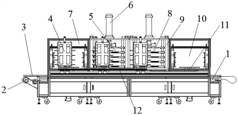
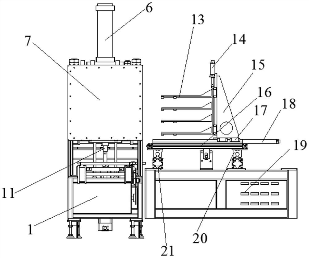
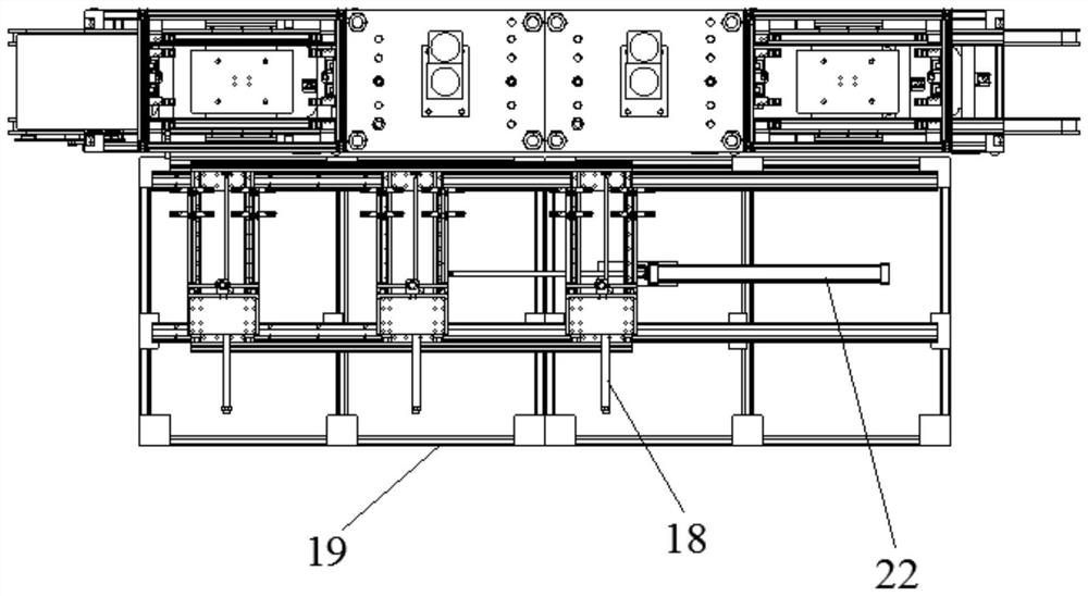
[0022] see Figure 1-5 , in an embodiment of the present invention, a stamping equipment for a computer case shield, which includes a flow-type conveying table 1, a clamping and transferring mechanism 4, a jacking and lifting mechanism, a stamping hydraulic cylinder 6, a hole forming stamping die set 5, Stamping and shaping module 8, loading station 7 and unloading station 10, wherein, along the conveying direction of the flow-through conveyor table, there are successively provided feeding station 7, hole forming stamping station, and stamping and shaping station and the unloading station 10, wherein, the jacking and lifting mechanism located at the center of the width of the flow-through conveying platform is arranged in the loading station and the unloading station, wherein the The hole forming stamping station is provided with a hole forming stamping die set 5, the stamping shaping station is provided with the stamping shaping die set 8, and the hole forming stamping die se...


PUM


Abstract

The invention discloses a stamping device for computer case guard plates, which realizes simultaneous stamping processing of multiple blank plates at one time, and adopts a manipulator for automatic transfer, which improves the efficiency of blank transfer and stamping. The invention sets anti-recoil The dislocation mechanism, the anti-recoil dislocation mechanism is configured to enable the stamping hydraulic cylinder to simultaneously stamp multiple blank plates, and the blank plate in the lower layer and the forming die in the lower layer react to the forming die and blank plate above it. The impact force causes the blank plate to be dislocated, which can effectively prevent the adverse effects of simultaneous stamping on multiple blank plates. The anti-recoil dislocation mechanism includes an anti-recoil driver and a detection and trigger mechanism. By setting the detection and trigger mechanism, it can be The driving action time of the anti-recoil driver is located immediately after the action of the stamping hydraulic cylinder, so as to prevent the impact of the recoil force on the recoil action of the stamping hydraulic cylinder from causing the misalignment of the forming die and the blank plate.

Description

technical field [0001] The invention specifically relates to a stamping equipment for a computer case guard plate, belonging to the technical field of stamping equipment. Background technique [0002] For the protective plate of the computer case, since it is a sheet metal part, when it is formed, it is generally formed by stamping. The current stamping equipment generally uses stamping dies and stamping hydraulic cylinders for stamping and forming. Although this stamping and forming method is simple, it generally requires manual loading during stamping, and each stamping can only realize the stamping of one workpiece. This results in lower punching efficiency, and if a plurality of stamping dies are simply stacked up and down together, when stamping, due to the stamping hydraulic cylinder pressing down, due to the setting of the multi-layer stamping die and the blank, the stamping die will After pressing, the stamping die in the lower part will produce a large recoil force...

Claims


Application Information

Patent Timeline
Patent Type & Authority Patents(China)
IPC IPC(8): B21D35/00B21D28/34B21D22/02B21D43/02B21D43/10
CPCB21D35/001B21D35/002B21D28/34B21D22/02B21D43/027B21D43/105
Inventor 李俊翰
Owner CHONGQING COLLEGE OF ELECTRONICS ENG
Why Eureka
Try Eureka