Light steel keel foundation structure system of light partition wall and construction method

A light steel keel and foundation structure technology, which is applied in the direction of walls, building components, building structures, etc., can solve the problems of inaccurate lap joint position, uneven keel surface, poor finish surface flatness, etc., and achieve fast construction and installation. The effect of high construction precision and flat installation surface

Active Publication Date: 2016-04-20
DONGGUAN VANKE BUILDING TECHN RES +1
View PDF6 Cites 10 Cited by
  • Summary
  • Abstract
  • Description
  • Claims
  • Application Information

AI Technical Summary

Problems solved by technology

[0003] 1. The construction is troublesome. The traditional construction method requires manual drilling for keel and keel lap, and then pulls rivets to connect, which is labor-intensive and time-consuming
[0004] 2. The construction accuracy is low, the traditional method does not have any positioning, limit tools, methods, and completely depends on the on-site control of the construction personnel, and there is a large risk of human error. The site causes inaccurate positioning of the keel, inaccurate overlapping positions, incorrect overlapping methods, etc., The overall precision of the keel is low,
[0005] 3. The surface of the keel is uneven. The traditional method of keel connection nail head or fixed point is raised and deformed, resulting in uneven finish surface of the keel. Covering the uneven keel surface will inevitably result in poor flatness of the finished surface after cladding.
[0006] The above are the key problems of the traditional light steel keel system. The above problems lead to low construction efficiency of the light steel keel system, difficulty in controlling the construction quality, and high requirements for construction personnel.

Method used


Image

  • Light steel keel foundation structure system of light partition wall and construction method
  • Light steel keel foundation structure system of light partition wall and construction method
  • Light steel keel foundation structure system of light partition wall and construction method

Examples


Embodiment Construction

[0030] In order to illustrate the technical solution of the present invention more clearly, the technical solution of the present invention will be further described in detail below in conjunction with the accompanying drawings and embodiments. Obviously, the following descriptions are only some embodiments of the present invention. In other words, other embodiments can also be obtained according to these embodiments without paying creative efforts.

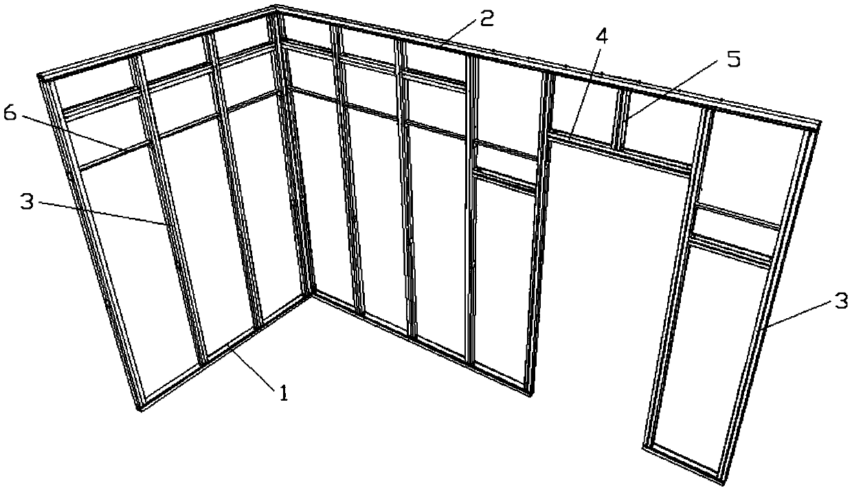
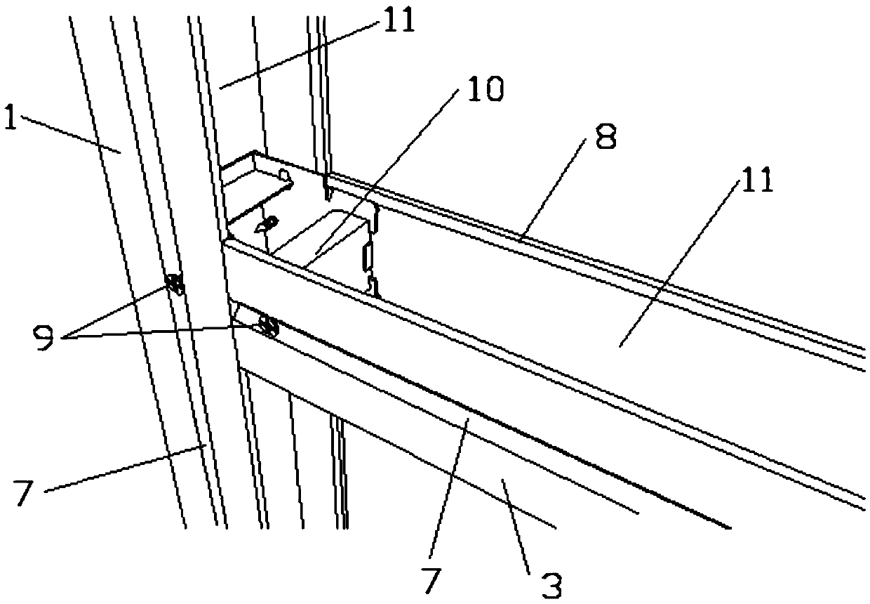
[0031] refer to Figure 1 to Figure 8 , a light steel keel foundation structure system for lightweight partition walls, used for lightweight partition wall systems, especially suitable for various wall panels with a thickness of 10mm to 30mm; the light steel keel of the lightweight partition wall The basic structure system includes the heaven and earth keel and the vertical keel 3 vertical keel 4 vertical keel 5, the sky and earth keel and the vertical keel 3 vertical keel 4 vertical keel 5 are all U-shaped groove 11 structures w...


PUM


Abstract

The invention discloses a light steel keel foundation structure system of a light partition wall and a construction method. The light steel keel foundation structure system of the light partition wall comprises a roof-ground keel and vertical keels; the roof-ground keel comprises a ground keel and a top keel, the vertical keels are connectedly arranged between the ground keel and the top keel through first connecting pieces, and the vertical keels are connected and fixed to one another through the first connecting pieces and / or second connecting pieces; V-grooves are symmetrically arranged on two sides walls of the roof-ground keel, and V-grooves are arranged in two sides walls and the bottom of each vertical keel. The keel finished surface of the light steel keel foundation structure system of the light partition wall is free of any protruding nail heads and salient points, foolproof installation and smoothness of the keel structure closure plate mounting surface are realized, wall flatness can reach + / -2mm after the light steel keel foundation structure system of the light partition wall is covered with boards, wallpaper can be paved directly, and simplicity in construction and rapidness in installation are realized.

Description

technical field [0001] The invention relates to a wall structure, in particular to a light steel keel foundation structure system and a construction method for a lightweight partition wall of a lightweight partition wall system. Background technique [0002] The existing light steel keel partition wall system using various keels has the following disadvantages: [0003] 1. The construction is troublesome. The traditional construction method requires manual drilling for keel and keel lap, and then pulls rivets to connect, which is labor-intensive and time-consuming [0004] 2. The construction accuracy is low, the traditional method does not have any positioning, limit tools, methods, and completely depends on the on-site control of the construction personnel, and there is a large risk of human error. The site causes inaccurate positioning of the keel, inaccurate overlapping positions, incorrect overlapping methods, etc., The overall precision of the keel is low, [0005] 3...

Claims


Application Information

Patent Timeline
Patent Type & Authority Applications(China)
IPC IPC(8): E04B2/76E04B2/78
CPCE04B2/76E04B2/766E04B2/78E04B2/767E04B2/789E04B2/7457
Inventor 时宇黄成孙江平邵叶田双喜
Owner DONGGUAN VANKE BUILDING TECHN RES
Why Eureka
Try Eureka