Gearbox based on hydraulic transmission

A technology of hydraulic transmission and gearbox, applied in the field of gearboxes, can solve the problems of large size, no, and too large distance of the gearbox.

Active Publication Date: 2016-04-20
桐乡市尚艺家纺产业服务有限公司
View PDF4 Cites 5 Cited by
  • Summary
  • Abstract
  • Description
  • Claims
  • Application Information

AI Technical Summary

Problems solved by technology

The gearbox includes the input shaft, the output shaft and the transmission structure between the two, resulting in a large volume of the entire gearbox. When installing, it is often forced to determine the installation position first due to space constraints, and then because of the distance between the power source and the gearbox. It should not be too large, and the position of the gearbox dete

Method used


Image

  • Gearbox based on hydraulic transmission
  • Gearbox based on hydraulic transmission
  • Gearbox based on hydraulic transmission

Examples


Embodiment Construction

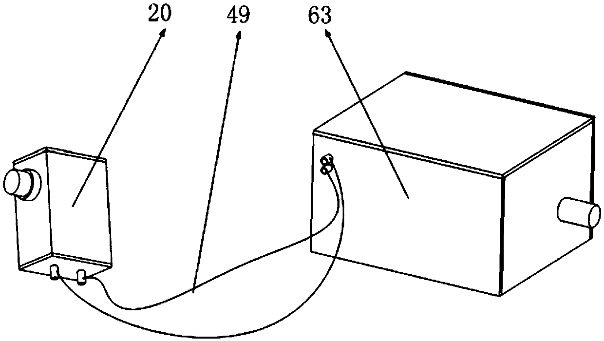
[0037] Such as figure 1 As shown, it includes a first torque hydraulic conversion mechanism, a fluid conduit, and a gearbox, wherein the first torque hydraulic conversion mechanism is connected to the gearbox through a fluid conduit.

[0038] The torque hydraulic conversion mechanism in the present invention can convert energy between the torque of the rotating shaft and the flow of the liquid, and the first torque hydraulic conversion mechanism converts the rotational speed and torque of the power input shaft of the power source into the reciprocating flow of the liquid in the liquid conduit , the reciprocating liquid communicates with the second torque hydraulic conversion mechanism in the gearbox through the liquid conduit. The gears realize the speed change.

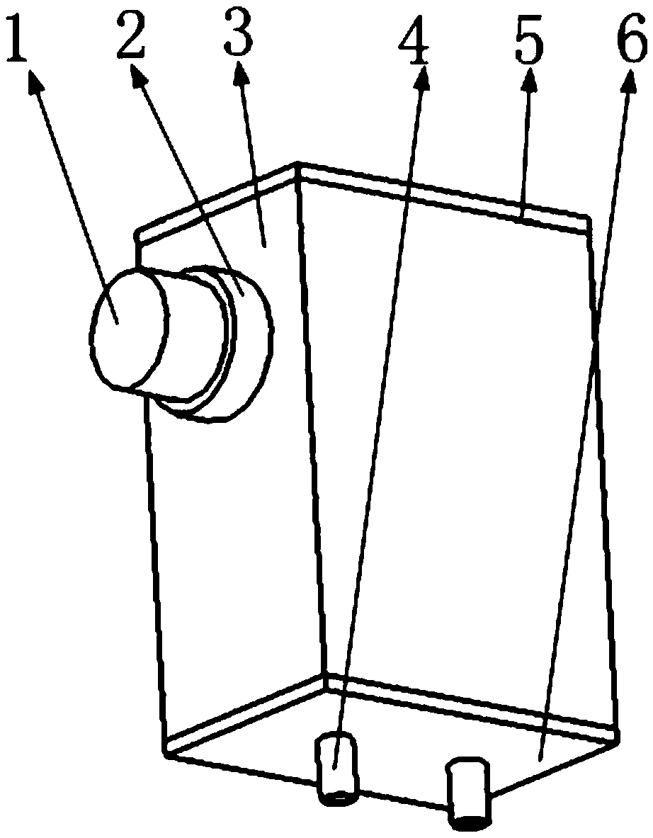
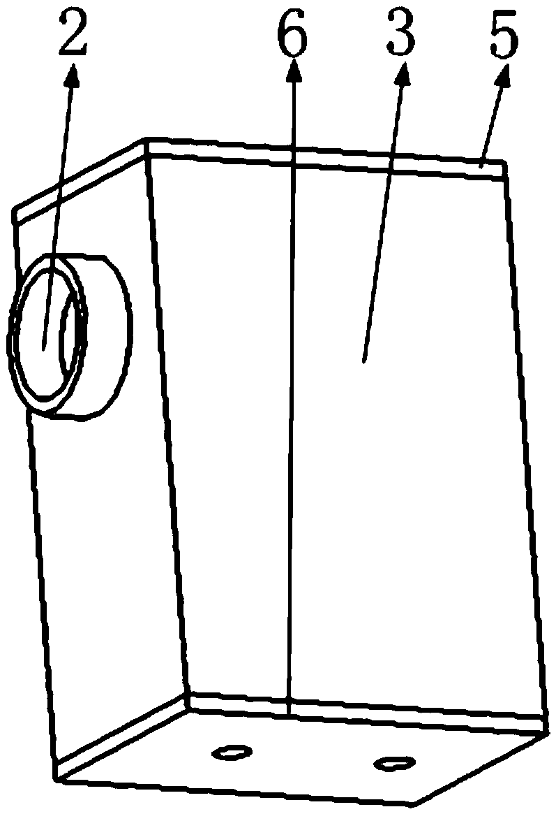
[0039] Such as Figure 5 As shown, the above-mentioned first torque hydraulic conversion mechanism includes the first hydraulic transmission shaft, the sleeve of the hydraulic transmission shaft, the outer wall of ...


PUM


Abstract

The invention belongs to the technical field of transmissions, and particularly relates to a gearbox based on hydraulic transmission. The gearbox comprises two torque hydraulic conversion mechanisms, a first liquid duct, a gearbox body, a driving gear, a transmission gear, a base and a second liquid duct, the torque hydraulic conversion mechanisms convert between rotation of a transmission shaft and reciprocating flow of liquid, and when the torque hydraulic conversion mechanisms are in matched use, torque transmission effect of the transmission shaft in complex spatial distribution can be realized; the gearbox is designed to have three gears, and three transmission gears and one driving gear are meshed; the driving gear is mounted on a combination base which can move transversely and longitudinally, and the driving gear moves along a plane of the base to selectively drive one of the three transmission gears to realize gear shifting. The liquid duct is connected with the transmission shaft to separate out a power input shaft in the gearbox, mounting flexibility of the gearbox is improved, and the gearbox has a good application prospect.

Description

Technical field [0001] The invention belongs to the technical field of gearboxes, in particular to a gearbox based on hydraulic transmission. Background technique [0002] At present, the positions of the power input shaft and the output shaft in the automobile gearbox are relatively fixed, and a moving transmission gear is added between the two shafts, and the movement of the transmission gear realizes the speed change of the gearbox. The gearbox includes the input shaft, the output shaft and the transmission structure between the two, resulting in a large volume of the entire gearbox. When installing, it is often forced to determine the installation position first due to space constraints, and then because of the distance between the power source and the gearbox. It should not be too large, and the position of the gearbox determines the position of the power source, and then other equipment is installed; the position of the gearbox and the power source basically determines...

Claims


Application Information

Patent Timeline
IPC IPC(8): F16H47/02
CPCF16H47/02
Inventor 柳超
Owner 桐乡市尚艺家纺产业服务有限公司
Why Eureka
Try Eureka