
Large impact load distribution mechanism

A technology of load distribution and large impact, applied to rocket launchers, offensive equipment, weapon types, etc.

Active Publication Date: 2018-03-13
BEIJING INST OF SPACE LAUNCH TECH +1
View PDF5 Cites 0 Cited by
  • Summary
  • Abstract
  • Description
  • Claims
  • Application Information

AI Technical Summary

Problems solved by technology

[0003] The purpose of the present invention is to provide a large impact load distribution mechanism to solve the problem of load distribution when the impact is large

Method used


Image

  • Large impact load distribution mechanism
  • Large impact load distribution mechanism
  • Large impact load distribution mechanism

Examples


Embodiment Construction

[0021] The present invention will be described in further detail below through specific embodiments in conjunction with the accompanying drawings.

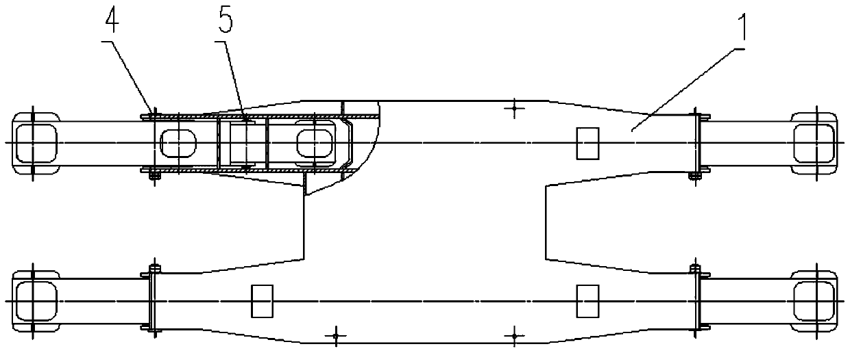
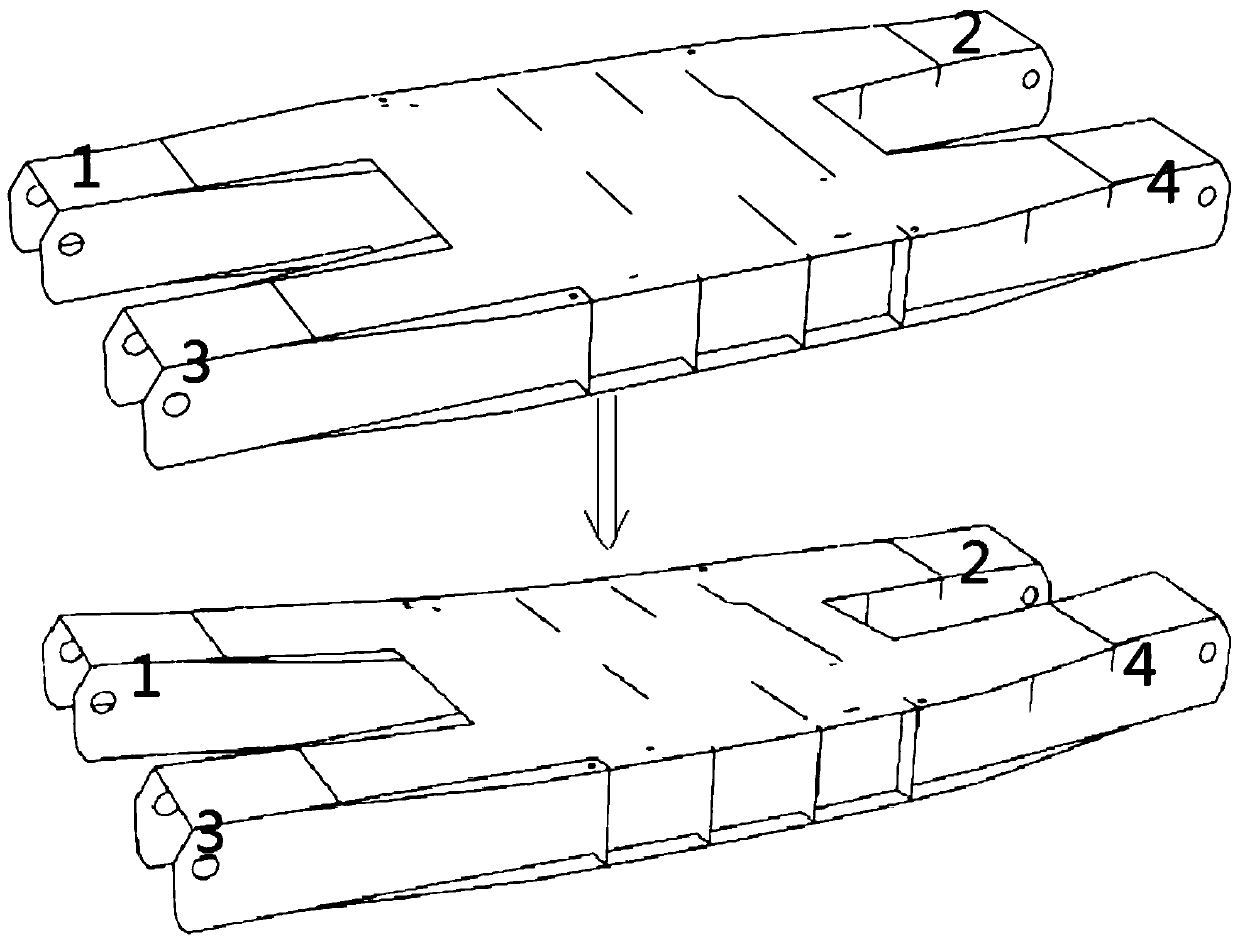
[0022] A large impact load distribution mechanism, which is a large box-shaped welded beam structure, multi-level load beams, each level has multiple load beams; all load beams of the same level are in the same load surface; two adjacent levels The load beams are connected by pin shafts, and the lower load beams share the load of the upper load beams connected with the pin shafts; the upper and lower adjacent two-stage load beams use the pin shafts as fulcrums to form a lever structure.

[0023] It has the function of dispersing and guiding the large impact load carried by the upper part of the product to the lower structure in a specific proportion, thereby reducing the local load of the lower structure and ensuring its service life to meet the launch requirements. The load distribution mechanism needs to meet the high impact bea...


PUM


Abstract

The invention relates to the field of high impact load distribution, particularly a high-impact-load distributing mechanism which is a large-size box-type welded beam structure. The high-impact-load distributing mechanism is composed of a plurality of stages of load beams, wherein each stage is provided with a plurality of load beams; all the load beams on the same stage are positioned on one load surface; the load beams of the upper and lower adjacent stages are connected through axis pins, the load beams below share the load of the load beam above connected with the axis pin; and the load beams of the upper and lower adjacent stages constitute a lever structure by using the axis pin as the pivot. The high-impact-load distributing mechanism has the functions of dispersing the high impact load carried above the product according to the specific proportion and leading the high impact load to the lower structure, thereby reducing the local load of the lower structure, ensuring the service life and further satisfying the launching requirement.

Description

technical field [0001] The invention relates to the field of load distribution, in particular, to a large impact load distribution mechanism. Background technique [0002] Aerospace products will impact the product carrying facilities before take-off, and excessive impact will cause damage to the structure of the facilities. Before the present invention was produced, no specific measures were adopted to avoid the above-mentioned damage, and the load was only carried by four legs of the bearing facility. When the impact is too large, the load transmitted by the four outriggers is too large, causing damage to the local bearing facilities. Contents of the invention [0003] The purpose of the present invention is to provide a large impact load distribution mechanism to solve the problem of load distribution when the impact is relatively large. [0004] The invention provides a large impact load distribution mechanism, which is a welded beam structure, including multi-level ...

Claims


Application Information

Patent Timeline
Patent Type & Authority Patents(China)
IPC IPC(8): F41F3/04
CPCF41F3/04
Inventor 张筱马广亮何冠杰王南马跃峰
Owner BEIJING INST OF SPACE LAUNCH TECH
Learn More