
A Fiber Bragg Grating Pressure Sensor

A technology of pressure sensor and optical fiber grating, which is applied in the field of pressure monitoring in pipelines/equipment, can solve the problem of low sensitivity, achieve the effect of improving sensitivity, improving measurement accuracy, and reducing random errors

Active Publication Date: 2019-03-12
PIPECHINA SOUTH CHINA CO +1
View PDF7 Cites 2 Cited by
  • Summary
  • Abstract
  • Description
  • Claims
  • Application Information

AI Technical Summary

Problems solved by technology

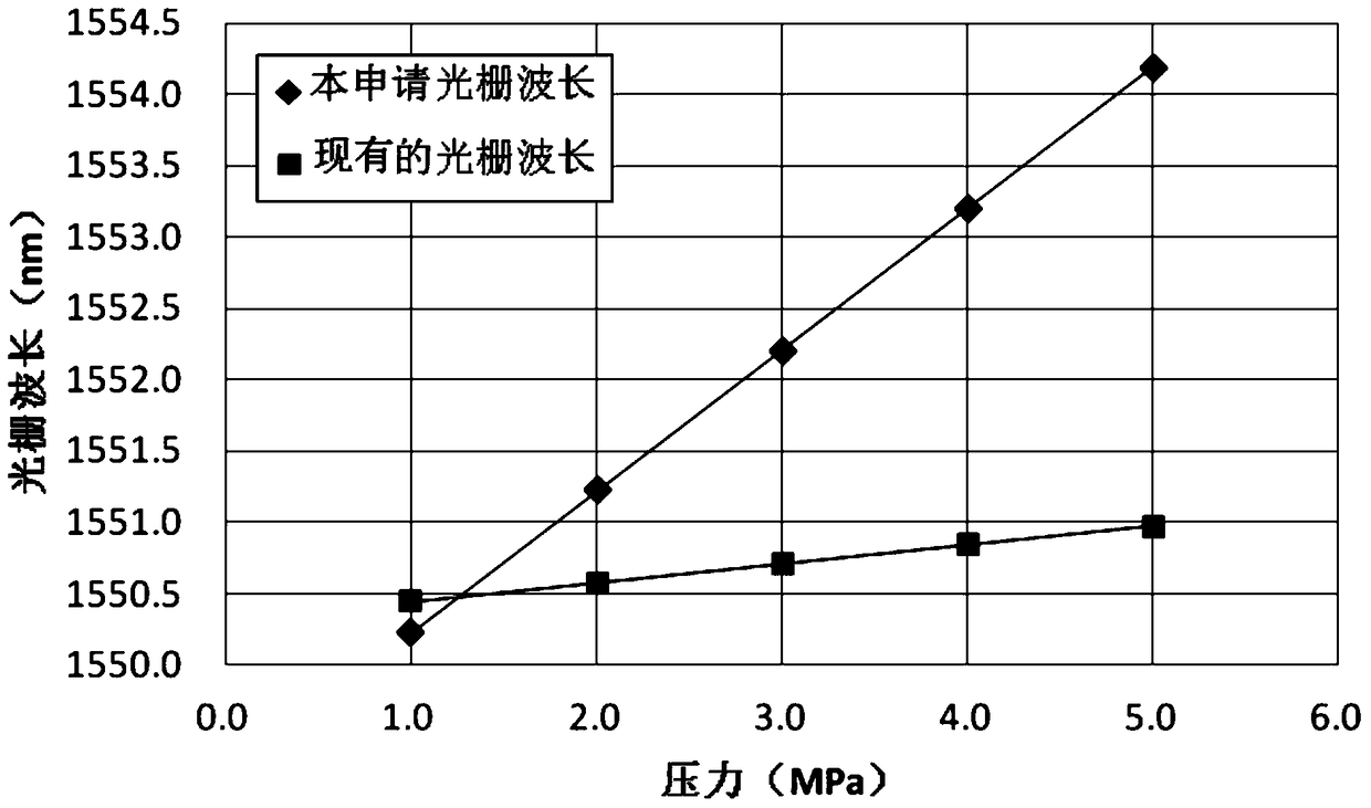
[0004] The embodiment of the present application provides a fiber grating pressure sensor for monitoring the pressure in a pipeline or equipment, which solves the technical problem of low sensitivity of the fiber grating pressure sensor in the prior art

Method used


Image

  • A Fiber Bragg Grating Pressure Sensor
  • A Fiber Bragg Grating Pressure Sensor
  • A Fiber Bragg Grating Pressure Sensor

Examples


Embodiment 1

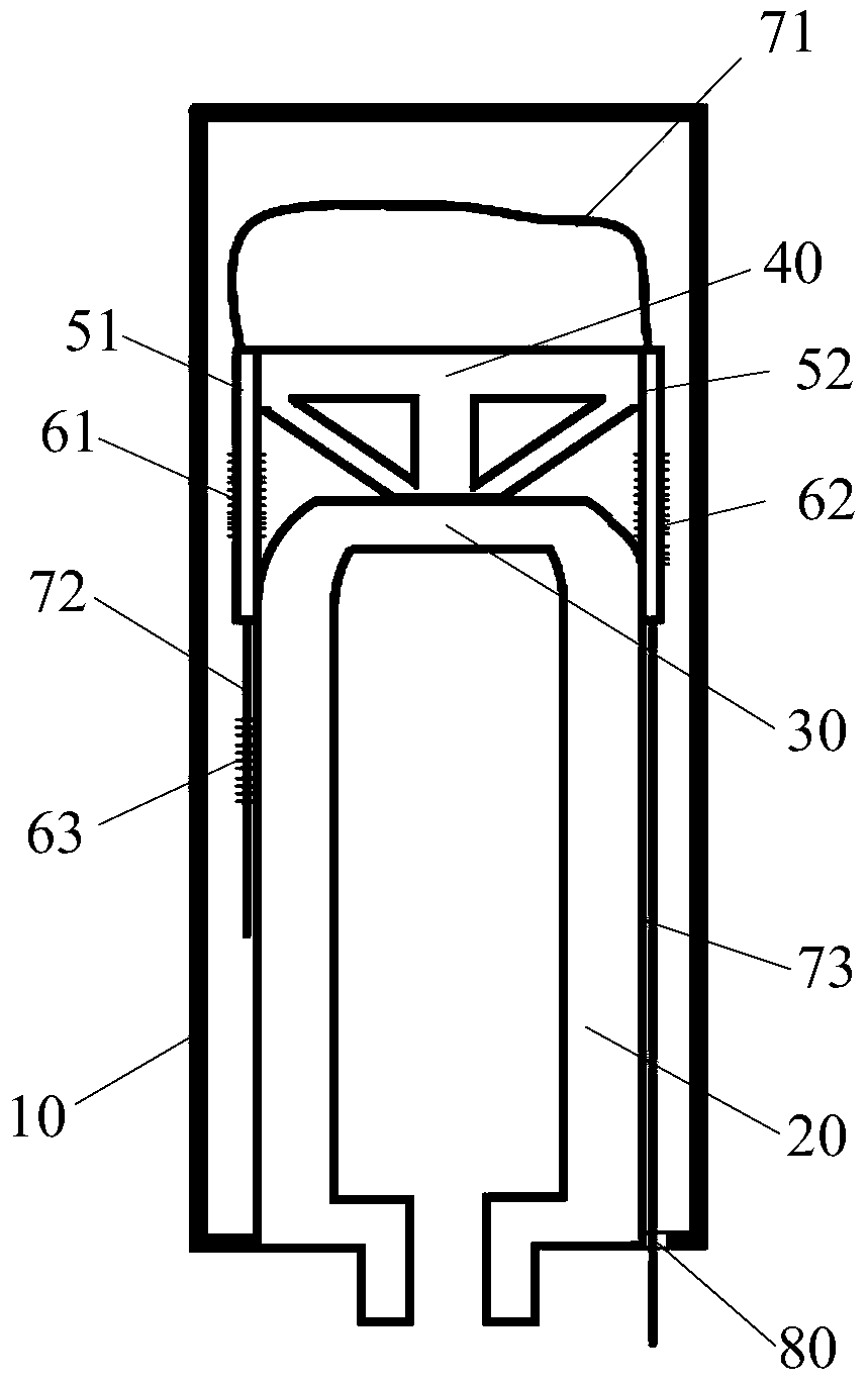
[0049] This embodiment provides a fiber grating pressure sensor, which communicates with the pressure-tested pipeline, or the pressure-tested pipeline container, or the pressure-tested pipeline equipment, and is used for measuring the pressure-tested pipeline, or the pressure-tested pipeline container, or the pressure-tested pipeline The pressure in the pressure measuring pipeline equipment is tested.

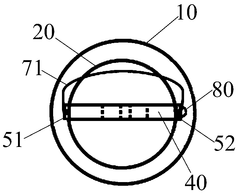
[0050] further, such as Figure 1-2 As shown, the fiber grating pressure sensor includes:

[0051] The pressure chamber 20 communicates with the pressure-tested pipeline, or the pressure-tested pipeline container, or the pressure-tested pipeline equipment;

[0052] The flat diaphragm 30 is fixed on the pressure chamber 20;

[0053] The bracket 40 is fixed on the flat diaphragm 30 and is located at the center of the flat diaphragm 30;

[0054] The first connecting piece 51 and the second connecting piece 52 are symmetrically fixed at the two ends of the support 40; The side of...


PUM

PropertyMeasurementUnit
Sensitivityaaaaaaaaaa

Abstract

The invention discloses a fiber grating pressure transducer, comprising a pressure chamber; a flat diaphragm fixed on the pressure chamber; a rack fixed on the flat diaphragm and located in the center of the flat diaphragm; a first connection sheet fixed to one end of the rack, wherein one end of the first connection sheet is in connection with the top rod side of the rack, and the other end of the first connection sheet is in connection with the sidewall top terminal of the pressure chamber; a first fiber grating fixed to the first connection sheet, and used for sensing the center displacement of the flat diaphragm so as to obtain the pressure change of a current pressure chamber, and reflecting the pressure change of the current pressure chamber through the reflection wavelength change of the first fiber grating. Compared with the fiber grating pressure transducer of the prior art, the fiber grating pressure transducer possesses the advantages of high sensitivity, sound stability, great anti-interface capability and proneness to web forming.

Description

technical field [0001] The invention relates to the technical field of pressure monitoring in pipelines / equipment, in particular to an optical fiber grating pressure sensor. Background technique [0002] Fiber Bragg grating sensor is a kind of fiber optic sensor, which is a wavelength modulation fiber optic sensor. Fiber Bragg grating sensors obtain sensing information by modulating the wavelength of the fiber Bragg (Bragg) with external physical parameters. Compared with electronic sensors, fiber grating sensors are more suitable for use in harsh environments such as oil, gas and petrochemical industries or high temperature and high pressure. [0003] In the prior art, most of the fiber grating sensors use the measurement principle of the pipe wall strain change to inversely calculate the pressure in the pipe to detect the pressure in the pipe (for example: Patent No. 99807831.X), which has the disadvantage of low sensitivity. Contents of the invention [0004] An embod...

Claims


Application Information

Patent Timeline
Patent Type & Authority Patents(China)
IPC IPC(8): G01L11/02
CPCG01L11/025
Inventor 闵希华路民旭黄忠胜陈迎锋林小飞杨阳谢萍王修云陈超声胡春平刘洋马国立
Owner PIPECHINA SOUTH CHINA CO
Learn More