
Capturing rod structure

A technology of supporting pipes and ear plates, which is applied in the direction of devices for guiding ships to the water surface, etc., can solve the problems of not meeting the requirements of speed and safety of official ships, inconvenient recovery of small boats at sea, and troublesome operation

Active Publication Date: 2016-04-27
广州船舶及海洋工程设计研究院(中国船舶集团有限公司第六〇五研究院) +1
View PDF7 Cites 0 Cited by
  • Summary
  • Abstract
  • Description
  • Claims
  • Application Information

AI Technical Summary

Problems solved by technology

[0003] At present, the conventional methods for retracting and deploying working boats on official ships include towing type, crane type, davit type and stern chute type. Therefore, the working speed is slow, the operation is cumbersome and not safe enough, and it cannot be retracted and retracted when the sea conditions are bad or the mother ship is sailing, and it cannot meet the speed and safety requirements of official ships when law enforcement ; and the stern chute-type floating object retracting device, especially for the retraction and release of small boats at sea, mainly uses the stern of the hull as an auxiliary slideway, and a "concave"-shaped chute is set at the stern of the hull, which is flushed by small boats at sea. Sea boats can be retracted or released by means of platooning or traction. Since the stern slide only has a single inclined track, the small boats can be quickly flushed and discharged onto the track, and then recovered by traction. During the process, the impact force is large, and it is easy to cause damage to the track on the small boat and the stern slideway. In addition, in the environment of high sea conditions, it is difficult for the small boat at sea to align with the inclined track, which also brings inconvenience to the recovery of the small boat at sea.

Method used


Image

  • Capturing rod structure

Examples


Embodiment Construction

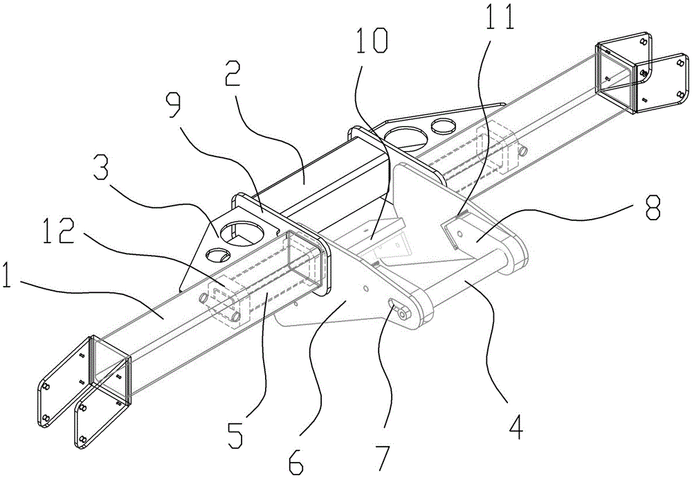
[0010] A snap-rod structure such as figure 1 As shown, it includes a square tubular support tube 1 connected to the bracket main body on both sides. The middle part of the two support tubes 1 is spaced apart and connected by connecting rods 2 on the outside thereof. The connecting rod 2 can also be a square tube, and the two ends are connected with the support pipe 1 at both ends through the gusset 3 to enhance the lateral strength and rigidity and protect the hook rod 4 from the impact of the lateral force. The opposite ends of the two support tubes 1 are respectively inserted and installed with square shafts 5, the shafts 5 and the support tube 1 form a nested structure, and the first shock absorber 12 is filled between the shaft 5 and the support tube 1; The end of the rod 5 protrudes from the opposite end of the support tube 1, and the protruding ends are respectively welded and fixed to two opposite lugs 6, and one end of the two opposite lugs 6 is respectively fixed to t...


PUM


Abstract

The invention relates to a capturing rod structure. The capturing rod structure comprises two square tuber support tubes of which two sides are connected with a bracket body, the middle parts of the two support tubes are separated, and are connected through an outside connecting rod; square axial rods are respectively inserted into the opposite ends of the two support tubes, and the axial rods and the support tubes form a nested structure; first cushion pads are stuffed between the axial rods and the support rods; the end parts of the two axial rods extend out from the opposite end parts of the support tubes, and the extending end parts are respectively and fixedly connected with two opposite lug plates; one ends of the two opposite lug plates are respectively and fixedly connected with the axial rods, and the other ends of the lug plates are provided with opposite slotted holes; a hooking and hanging rod is arranged at the middle parts of the two slotted holes, and after the two ends of the hooking and hanging rod penetrate through the opposite slotted holes, mounting fasteners are limited, and second cushion pads are arranged between the hooking and hanging rod and the lug plates at two ends, and are arranged along the extension directions of the lug plates; one ends of the second cushion pads are fixed to the lug plates, and the other ends penetrate through the hooking and handing rod.

Description

technical field [0001] The invention relates to a positioning and catching device for recovering floating objects on water in a device for receiving and releasing floating objects on water. Background technique [0002] Marine structures such as ships and offshore platforms often need to be equipped with relatively small and relatively flexible equipment due to functional requirements, such as offshore buoys, working boats, torpedoes, etc. It is especially commonly used on official ships (customs, sea surveillance, fishery administration, maritime affairs and public security frontier defense ships, etc.). Usually, official ships need to be equipped with 1 or 2 high-speed sea boats as working boats to make up for the low speed of large ships and Due to the larger hull, it is unable to perform tasks in shallow waters or narrow waters. [0003] At present, the conventional methods for retracting and deploying working boats on official ships include towing type, crane type, dav...

Claims


Application Information

Patent Timeline
IPC IPC(8): B63B23/30
CPCB63B23/30
Inventor 朱小楠卢孝武黎理胜钱雯陈万宏陈顺洪
Owner 广州船舶及海洋工程设计研究院(中国船舶集团有限公司第六〇五研究院)
Learn More