Lifting self-closing hinge for high-sealing door

A high-sealing and self-closing technology, which can be used in door/window accessories, wing shutters, buildings, etc., and can solve the problems of not being able to apply high-sealing doors

Inactive Publication Date: 2016-04-27
赵芬
View PDF8 Cites 3 Cited by
  • Summary
  • Abstract
  • Description
  • Claims
  • Application Information

AI Technical Summary

Problems solved by technology

The lifting hinge device directly uses the upper and lower shaft sleeves to realize the transfer. During installation, the two hinges are respectively installed on the inner side of the door frame and the outer side of the door body. In order to reserve a turning space, there must be a gap between the door body and the door frame Fix the small distance gap, which makes it impossible to apply to high-sealed doors

Method used


Image

  • Lifting self-closing hinge for high-sealing door
  • Lifting self-closing hinge for high-sealing door
  • Lifting self-closing hinge for high-sealing door

Examples


Embodiment 1

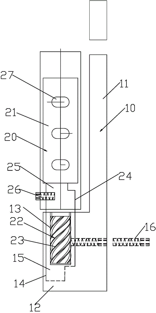
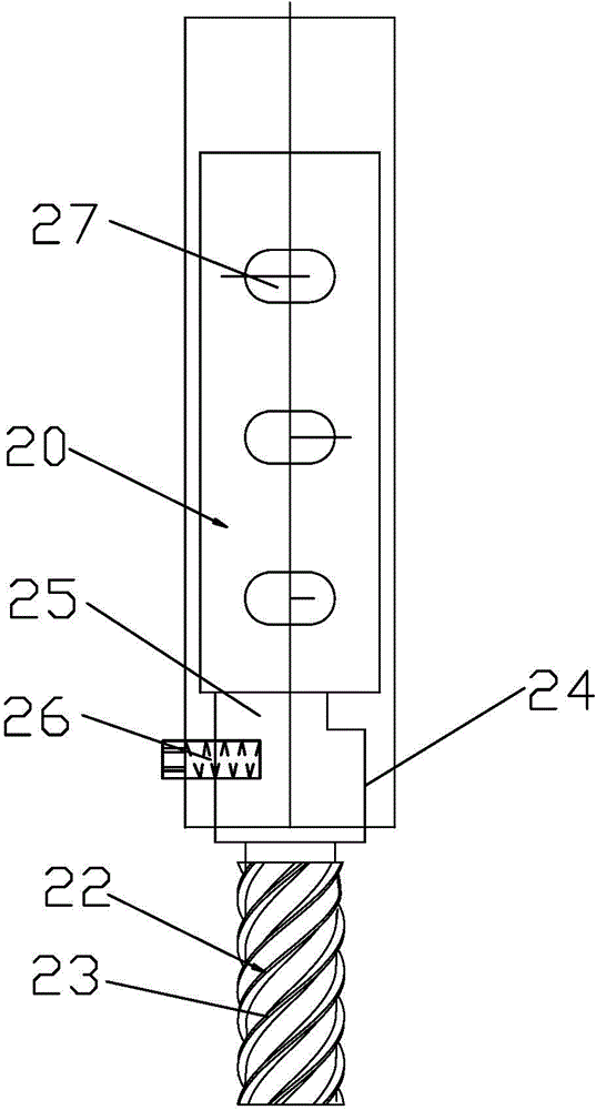
[0057] Please check Figure 1 to Figure 6 , High-sealed door lifting self-closing hinge, including a fixed part 10 and a rotating part 20.

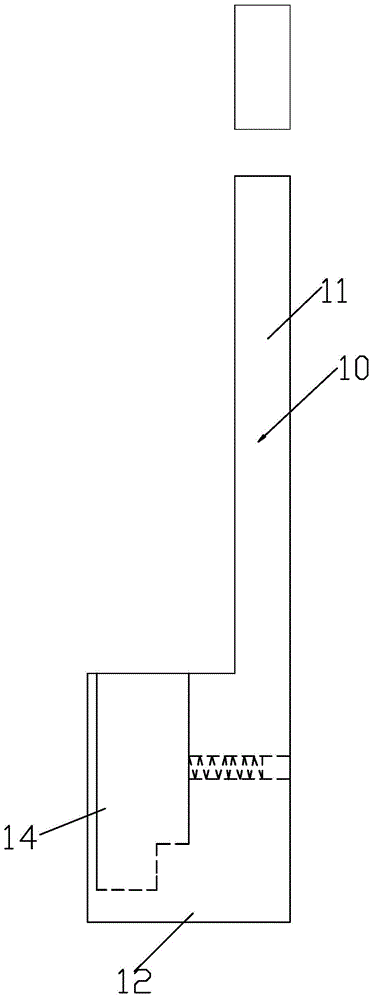
[0058] The fixed part 10 includes a fixed seat plate 11 and a convex seat 12 protruding from the front of the fixed seat plate 11 , and a screw hole 13 is recessed on the top surface of the vertical front of the convex seat 12 . In a specific structure, the convex seat 12 is protrudingly arranged on the lower part of the front of the fixed seat plate 11, and the part of the front of the fixed seat plate 11 above the convex seat 12 is provided with a through first lock hole, and the screw is used to pass through the first lock. The hole can fix the back of the fixed seat plate and the front face of the door frame to abut together. The top surface of the convex seat 12 is concavely provided with a first installation groove 14, and a screw hole sleeve 15 is installed in the first installation groove 14. The screw hole sleeve 15 is opened up...

Embodiment 2

[0063] Please check Figure 7 to Figure 11 , High-sealed door lifting self-closing hinge, including a fixed part 10 and a rotating part 20. It differs from the first embodiment in that it further includes an elastic body, which is a compression spring 30 .

[0064] The convex seat 12 is protrudingly arranged in the middle part of the front of the fixed seat plate 11, and the upper and lower parts of the front of the fixed seat plate 11 are provided with a through first lock hole, through which the back of the fixed seat plate 11 can be locked. It is fixedly connected to the front end of the door frame; the rotating part 20 also includes a hinge leaf 28 fixedly connected to the rotating seat 21, and the hinge leaf 28 is provided with a second lock hole 27 through which the hinge leaf can be locked. Sheet 28 is affixed to the door body. When the hinge was at 0 degrees, the fixed surface of the hinge leaf was flush with the back of the fixed seat plate.

[0065] The compressio...

Embodiment 3

[0068] Please check Figure 12 to Figure 13 , High-sealed door lifting self-closing hinge, including a fixed part 10 and a rotating part 20. It differs from the second embodiment in that no elastic body is provided, and the above-mentioned solid cup, screw rod and nut are not needed. The fixed part 10 includes a fixed seat plate and a convex seat protruding from the front of the fixed seat plate. A solid rod is fixedly installed on the top of the convex seat. The protruding part of the front has an external thread section 13'; the rotating part 20 includes a rotating seat, and the bottom surface of the rotating seat is concavely provided with a screw hole 23', and the external thread section 13' is screwed into the screw hole 23 '. When the hinge is at 0 degrees, the fixed surface of the hinge leaf and the back side of the fixed seat plate are parallel and spaced apart.

[0069] The hinge shown in the figure is a convex door hinge and the door is opened on the right. When t...


PUM


Abstract

The invention discloses a lifting self-closing hinge for a high-sealing door. The lifting self-closing hinge comprises a fixed part and a rotary part, wherein the fixed part comprises a fixed seat plate and a protruded base which is protruded on the front surface of the fixed seat plate; a screw hole is formed in the top surface of the perpendicular front surface of the protruded base in a sunken mode; the rotary part comprises a rotary base; a fixed rod is fixedly arranged on the bottom of the rotary base; the fixed rod is provided with an extending-out part which downwards extends out of the bottom surface of the rotary base; the extending-out part is provided with an outer threaded section; and the outer threaded section is in screw joint to a screw hole. The lifting self-closing hinge has the advantages that: the protruded base is arranged on the front surface of the fixed seat plate of the fixed part in the protruded mode, the rotary base is positioned on the protruded base, and the threaded section is in screw joint fit to the screw hole, so that the hinge can be designed to be applied to a high-sealing type protruded door or a flat door.

Description

technical field [0001] The invention relates to a high-seal type door lifting self-closing hinge. Background technique [0002] The China Patent Database announced a utility model named "A Lifting Hinge Device" and the patent number is 2013208356551. It includes an upper hinge, a lower hinge, a transmission seat and a transmission rod. The upper hinge includes the upper shaft sleeve and the upper hinge piece fixedly connected to the upper shaft sleeve; the lower hinge includes the lower shaft sleeve and the lower hinge piece fixedly connected to the lower shaft sleeve; the transmission seat is fixedly connected to the upper shaft sleeve, and the bottom of the transmission seat The end face is concavely provided with a transmission cavity, and the rotary surface inside the transmission cavity is provided with a first helical part. The transmission rod is fixedly connected to the lower shaft sleeve, and the outer rotating surface of the transmission rod is provided with a se...

Claims


Application Information

Patent Timeline
Patent Type & Authority Applications(China)
IPC IPC(8): E05F1/06
Inventor 吴芷靖
Owner 赵芬
Why Eureka
Try Eureka