Strength experiment clamp with double-head stud convenient to replace

A double-headed stud, strength test technology, applied in the direction of strength characteristics, measuring devices, instruments, etc., can solve the problems affecting the efficiency of bolt tension test, the connection efficiency of bolt and hydraulic testing machine is not high, and achieve the effect of convenient stress loading

Inactive Publication Date: 2016-04-27
CHENGDU HENGTONG ZHAOYE PRECISION MACHINERY
View PDF8 Cites 1 Cited by
  • Summary
  • Abstract
  • Description
  • Claims
  • Application Information

AI Technical Summary

Problems solved by technology

[0004] Aiming at the tensile mechanical performance detection of finished bolts in the above-mentioned prior art, the hydraulic testing machine is generally used in the prior art for measurement. However, the connection efficiency between the bolt and the hydraulic testing machine in the prior art is not high, which affects the performance of the bolt tensile test. In order to solve the problem of efficiency, the present invention provides a strength test fixture that can easily replace double-ended studs

Method used


Image

  • Strength experiment clamp with double-head stud convenient to replace

Examples


Embodiment 1

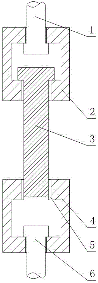
[0022] Such as figure 1 As shown, a strength test fixture that can easily replace double-ended studs includes a first block 2 and a second block 4, and the first block 2 and the second block 4 are respectively connected with first pull rods 1 and the second pull rod 6, the first pull rod 1 is used for the fixed connection between the first block 2 and the hydraulic testing machine, and the second pull rod 6 is used for the fixed connection between the second block 4 and the hydraulic testing machine; A pull rod 1 is used for stress transmission between the hydraulic testing machine and the first block 2, and a second pull rod 6 is used for stress transmission between the hydraulic testing machine and the second block 4; The axis of a pull rod 1 rotates, and the second block 4 can rotate relative to the axis of the second pull rod 6;

[0023] The first block 2 and the second block 4 are all provided with a T-shaped slot, the width of the bottom end of the T-shaped slot is grea...

Embodiment 2

[0028] Such as figure 1 As shown, this embodiment is further limited on the basis of Embodiment 1: in order to facilitate the uniformity of force on each point on the cross section of the first pull rod 1, the first block 2, the screw or the nut, the first pull rod 1 The axis of is collinear with the centerline of the T-shaped slot on the first clamping block 2 .

[0029] In order to facilitate the uniformity of the stress on the second pull rod 6, the second block 4, the screw rod or each point on the cross section of the nut, the axis of the second pull rod 6 is collinear with the center line of the T-shaped groove on the second block 4 .

[0030] In the absence of an auxiliary screw or nut, in order to make this fixture at least applicable to the tension test of a threaded rod with no nut end at both ends and a screw with a nut end at one end, T on the first block 2 A nut is arranged in the T-shaped slot and / or the T-shaped slot on the second block 4, and the nut is locat...


PUM


Abstract

The invention discloses a strength experiment clamp with a double-head stud convenient to replace. The strength experiment clamp comprises a first clamping block and a second clamping block, a first pull rod and a second pull rod are connected on the first clamping block and the second clamping block respectively, a T-shaped groove is formed in each of the first clamping block and the second clamping block, an internal threaded hole is formed in each of the first clamping block and the second clamping block, axis of the internal threaded hole in the first clamping block is parallel to the depth direction of the T-shaped groove in the first clamping block, axis of the internal threaded hole in the second clamping block is parallel to the depth direction of the T-shaped groove in the second clamping block, and each internal threaded hole is intersected with the bottom of the corresponding T-shaped groove. By adopting the structure, compared with directly connecting a bolt to a hydraulic experiment machine, efficiency in fetching and placing the bolt on the hydraulic experiment machine is ten times higher than that of conventional schemes; the strength experiment clamp can be conveniently applied to strength experiments of the double-head stud.

Description

technical field [0001] The invention relates to the technical field of an experimental platform for mechanical connectors, in particular to a strength test fixture that can conveniently replace double-ended studs. Background technique [0002] A bolt is a mechanical part, usually a cylindrical threaded fastener with a nut. The bolt is composed of two parts, the head and the screw rod (a cylinder with external threads). When used, it needs to cooperate with the nut to fasten and connect two parts with through holes. This connection form is called bolt connection. If the nut is unscrewed from the bolt, the two parts can be separated, so the bolt connection is a detachable connection. According to the way of connection force: divided into ordinary and hinged holes. According to the shape of the head: there are hexagonal head, round head, square head, countersunk head, etc. Among them, the hexagonal head is the most commonly used. At present, there are endless bolts used in ...

Claims


Application Information

Patent Timeline
IPC IPC(8): G01N3/04
CPCG01N3/04
Inventor 吴光武
Owner CHENGDU HENGTONG ZHAOYE PRECISION MACHINERY
Why Eureka
Try Eureka