Device for testing fatigue of connecting piece of one-arm three-dimensional measurement scribing instrument

A technology of three-dimensional measurement and test device, applied in the direction of measurement device, application of stable tension/pressure test material strength, instrument, etc., can solve the problems affecting the efficiency of bolt tensile test and the low connection efficiency of bolt and hydraulic testing machine, etc.

Inactive Publication Date: 2016-08-24
API ZC PRECISION INSTUMENT CO LTD
View PDF4 Cites 0 Cited by
  • Summary
  • Abstract
  • Description
  • Claims
  • Application Information

AI Technical Summary

Problems solved by technology

[0004] Aiming at the tensile mechanical performance detection of finished bolts in the above-mentioned prior art, the hydraulic testing machine is generally used in the prior art for measurement. However, the connection efficiency between the bolt and the hydraulic testing machine in the prior art is not high, which affects the performance of the bolt tensile test. To solve the problem of efficiency, the present invention provides a test device for single-arm three-dimensional measurement of the fatigue degree of the connecting part of the scribing instrument

Method used


Image

  • Device for testing fatigue of connecting piece of one-arm three-dimensional measurement scribing instrument

Examples


Embodiment 1

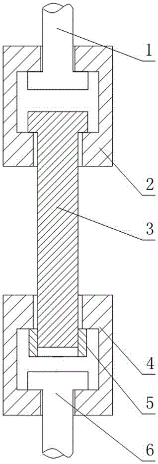
[0019] like figure 1 As shown, the test device for measuring the fatigue degree of the connecting part of the scribing instrument with a single arm three-dimensionally includes a first block 2 and a second block 4, and the first block 2 and the second block 4 are fixedly connected to the first block 2 and the second block 4 respectively. A pull rod 1 and a second pull rod 6, the first pull rod 1 is used for the fixed connection between the first block 2 and the hydraulic testing machine, and the second pull rod 6 is used for the fixed connection between the second block 4 and the hydraulic testing machine ;

[0020] The first block 2 and the second block 4 are all provided with a T-shaped slot, the width of the bottom end of the T-shaped slot is greater than the width of the opening end, and the depth direction of the T-shaped slot on the first block 2 is the same as that of the first block 2. The axial direction of a pull rod 1 is parallel, and the depth direction of the T-s...

Embodiment 2

[0024] like figure 1 As shown, this embodiment is further defined on the basis of Embodiment 1: in order to facilitate the uniformity of force on each point on the cross-section of the first pull rod 1, the first block 2, the screw or the nut 5, the first pull rod The axis of 1 is collinear with the centerline of the T-shaped slot on the first block 2.

[0025] In order to facilitate the uniformity of the stress on each point on the cross-section of the second pull rod 6, the second clamp block 4, the screw rod or the nut 5, the axis of the second pull rod 6 is in common with the center line of the T-shaped groove on the second clamp block 4. Wire.

[0026] In the absence of an auxiliary screw or nut 5, in order to make the clamp at least usable for the tension test of a threaded rod that is not provided with a 5 end of a nut at both ends, and a screw that is provided with a 5 end of a nut at one end, the first clamping block 2 A nut 5 is disposed in the T-shaped slot on the...


PUM


Abstract

The invention discloses a device for testing fatigue of a connecting piece of a one-arm three-dimensional measurement scribing instrument. The device comprises a first fixture block and a second fixture block, wherein a first pull rod and a second pull rod are respectively fixedly connected with the first fixture block and the second fixture block, the first pull rod is used for fixed connection between the first fixture block and a hydraulic testing machine, and the second pull rod is used for fixed connection between the second fixture block and the hydraulic testing machine; one T-shaped slot is respectively formed in each of the first fixture block and the second fixture block, the width of the bottom end of each T-shaped slot is larger than the width of the open end, the depth direction of the T-shaped slot in the first fixture block is parallel to axial direction of the first pull rod, the depth direction of the T-shaped slot in the second fixture block is parallel to the axial direction of the second pull rod; the first pull rod and the first fixture block are detachably connected; and the second pull rod and the second fixture block are detachably connected. By adopting the structure, compared with the condition that a direct connection bolt is connected with the hydraulic testing machine, efficiency of picking and placing bolts on the hydraulic testing machine is ten times higher than that of the traditional scheme; and structural style adopted by the device disclosed by the invention is convenient for complete set popularization.

Description

technical field [0001] The invention relates to the technical field of a mechanical connector experiment platform, in particular to a test device for three-dimensionally measuring the fatigue degree of a connector of a scribing instrument with a single arm. Background technique [0002] A bolt is a mechanical part, usually a cylindrical threaded fastener with a nut. The bolt is composed of two parts, the head and the screw rod (a cylinder with external threads). When used, it needs to cooperate with the nut to fasten and connect two parts with through holes. This connection form is called bolt connection. If the nut is unscrewed from the bolt, the two parts can be separated, so the bolt connection is a detachable connection. According to the way of connection force: divided into ordinary and hinged holes. According to the shape of the head: there are hexagonal head, round head, square head, countersunk head, etc. Among them, the hexagonal head is the most commonly used. ...

Claims


Application Information

Patent Timeline
IPC IPC(8): G01N3/04G01N3/10
CPCG01N3/04G01N3/10G01N2203/0048G01N2203/0073G01N2203/04
Inventor 刘宁周姝李德维张存多
Owner API ZC PRECISION INSTUMENT CO LTD
Why Eureka
Try Eureka