Optimization method and apparatus of airplane wing structure

A wing structure and optimization method technology, applied in design optimization/simulation, special data processing applications, instruments, etc., can solve problems such as unfavorable continuous processing of aircraft wings

Active Publication Date: 2016-04-27
BEIJING AERONAUTIC SCI & TECH RES INST OF COMAC +1
View PDF4 Cites 4 Cited by
  • Summary
  • Abstract
  • Description
  • Claims
  • Application Information

AI Technical Summary

Problems solved by technology

[0004] Different regions of the structure in the finite element model of the aircraft wing obtained by the above method have different thicknesses, resulting in the case that the thickness of adjacent regions in the same structure is a discrete value. However, the actual processing of the aircraft wing structure is formed by continuous processing , therefore, the finite element model of the aircraft wing obtained by the above method is not conducive to the actual continuous processing of the aircraft wing

Method used


Image

  • Optimization method and apparatus of airplane wing structure
  • Optimization method and apparatus of airplane wing structure
  • Optimization method and apparatus of airplane wing structure

Examples


Embodiment 1

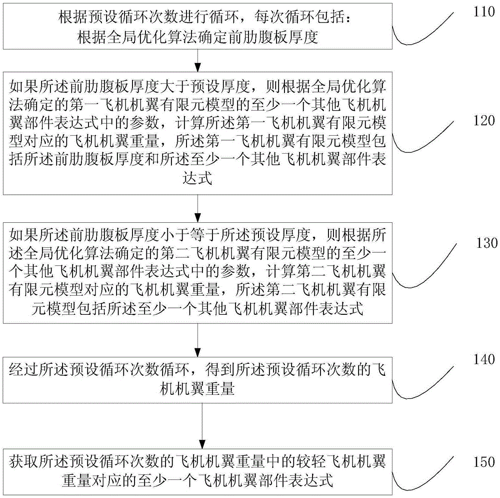
[0030] Figure 2A It is a flow chart of the method for optimizing the wing structure of an aircraft provided in Embodiment 1 of the present invention. This embodiment is applicable to the situation of optimizing the wing of an aircraft. The method can be executed by a program, and specifically includes the following steps:

[0031] Step 110, perform the cycle according to the preset number of cycles, and each cycle includes: determining the web thickness of the front rib according to the global optimization algorithm;

[0032] Specifically, the number of preset cycles is set in the user interface of the optimization software, for example, it can be set to 1000 times. When each cycle is executed, the thickness of the front rib web must be determined first, so as to find the specified aircraft wing finite element according to the thickness. The element model of the aircraft wing is optimized, and the finite element model of the aircraft wing that meets the requirements is obtain...

Embodiment 2

[0071] image 3 The flow chart of the optimization method for the aircraft wing structure provided by Embodiment 2 of the present invention. This embodiment is based on Embodiment 1. Before calculating the weight of the aircraft wing corresponding to the first aircraft wing finite element model, it is also Including the following steps:

[0072] Step 210, applying the at least one working condition load to the aircraft wing skin nodes constrained by root fixation.

[0073] According to the multi-condition loads checked by the strength, they are respectively applied to the skin nodes of the aircraft wing to form the load boundary conditions of the model; when the loads are applied, one type of load can be applied, or more than one type can be applied Condition load.

[0074] At the same time, the root of the aircraft wing is fixedly supported to form a constraint boundary condition, which is used to add boundary conditions to the subsequent static and buckling analysis of the...

Embodiment 3

[0102] Figure 4 The flow chart of the optimization method for the aircraft wing structure provided by Embodiment 3 of the present invention, this embodiment is based on Embodiment 1, and also includes the following steps before calculating the weight of the aircraft wing corresponding to the second aircraft wing finite element model :

[0103] Step 310, applying the at least one working condition load to the aircraft wing skin nodes constrained by root fixation.

[0104] According to the multi-condition loads checked by the strength, they are respectively applied to the skin nodes of the aircraft wing to form the load boundary conditions of the model; when the loads are applied, one type of load can be applied, or more than one type can be applied Condition load.

[0105] At the same time, the root of the aircraft wing is fixedly supported to form a constraint boundary condition, which is used to add boundary conditions to the subsequent static and buckling analysis of the ...


PUM


Abstract

The present invention discloses an optimization method and apparatus of an airplane wing structure. The method performs cycles according to the preset cycle number. Each cycle comprises the steps of determining and obtaining the thickness of a front rib web according to a global optimization algorithm; if the thickness of the front rib web is greater than a preset thickness, calculating airplane wing weight corresponding to a first airplane wing finite element model according to parameters, which are determined by the global optimization algorithm, of at least one other airplane wing part expression of the first airplane wing finite element model, the first airplane wing finite element model including the thickness of the front rib web and the at least one other airplane wing part expression; if the thickness of the front rib web is less than the preset thickness, entering a second airplane wing finite element model, and obtaining the airplane wing weights with the preset cycle number after the cycles of the preset cycle number; and obtaining at least one airplane wing part expression corresponding to the lighter airplane wing weight in the airplane wing weights with the preset cycle number.

Description

technical field [0001] Embodiments of the present invention relate to aircraft structure design technology, in particular to an optimization method and device for an aircraft wing structure. Background technique [0002] The aircraft wing structure includes: upper and lower skins, beam webs, rib webs, beam edge strips, skin stiffeners, etc. Among them, when obtaining the optimal finite element model of the aircraft wing, the upper and lower skin thickness, beam web thickness, rib web thickness, beam flange area, and skin stiffener area in the aircraft wing structure Divide into finite element elements of a certain shape and number connected by nodes to create a finite element model of the aircraft wing. [0003] Specifically, such as figure 1 The upper skin of the aircraft wing shown is divided into 3 regions, each region includes 9 finite element elements, and the thickness of the upper skin of the aircraft wing in each region is the same. Solve the thickness of each are...

Claims


Application Information

Patent Timeline
Patent Type & Authority Applications(China)
IPC IPC(8): G06F17/50
CPCG06F30/15G06F30/23
Inventor 邱菊胡震东
Owner BEIJING AERONAUTIC SCI & TECH RES INST OF COMAC
Why Eureka
Try Eureka