Intelligent optimization method and intelligent optimization device of positioning network element layout

An intelligent optimization and positioning network technology, applied in electrical components, network planning, wireless communication, etc., can solve the problems of weak global search ability, difficult to adjust, and the initial parameters of simulated annealing algorithm have a great influence on the final solution, so as to speed up the search. The effect of the optimal process

Active Publication Date: 2018-07-17
ZTE CORP
View PDF3 Cites 2 Cited by
  • Summary
  • Abstract
  • Description
  • Claims
  • Application Information

AI Technical Summary

Problems solved by technology

[0005] In summary, there are problems: (1) Since the existing intelligent optimization algorithm may stay on the local optimal solution with a high probability during the global search, the

Method used


Image

  • Intelligent optimization method and intelligent optimization device of positioning network element layout
  • Intelligent optimization method and intelligent optimization device of positioning network element layout
  • Intelligent optimization method and intelligent optimization device of positioning network element layout

Examples


Example

[0068] Application example 1:

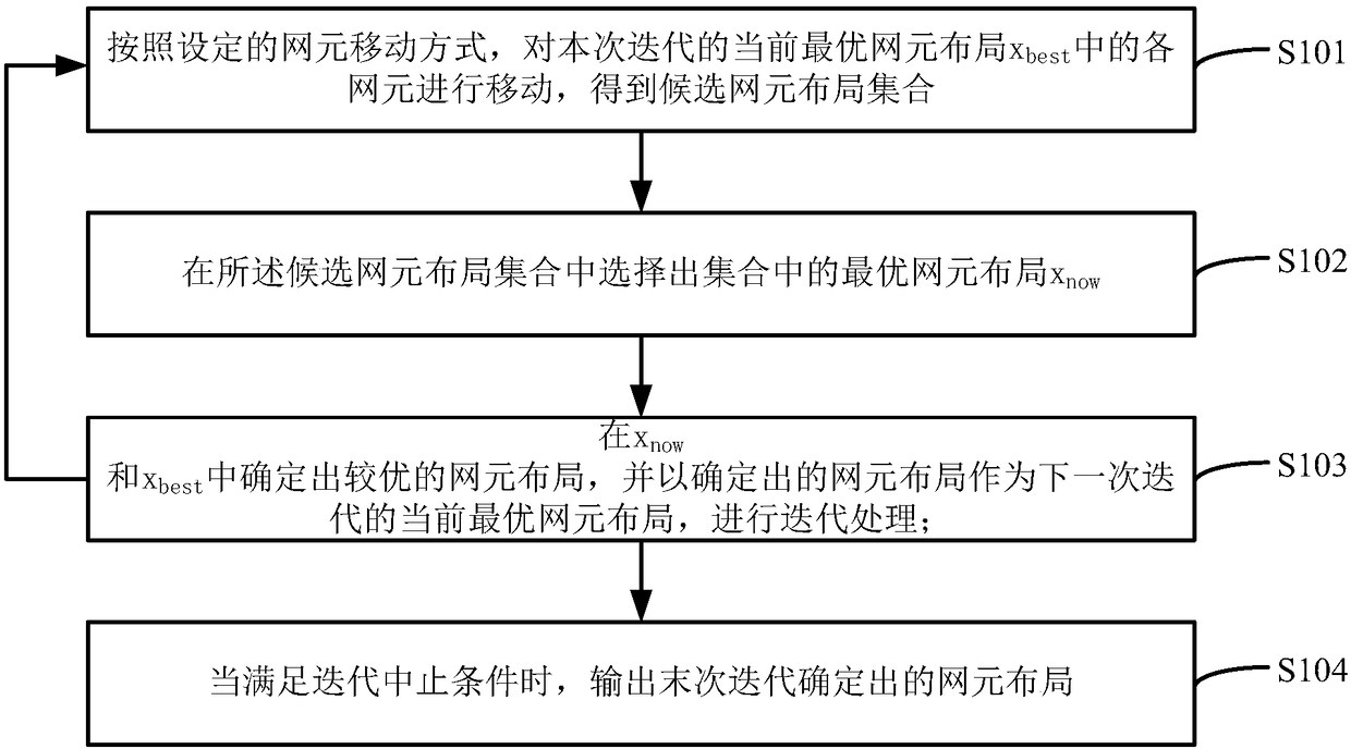
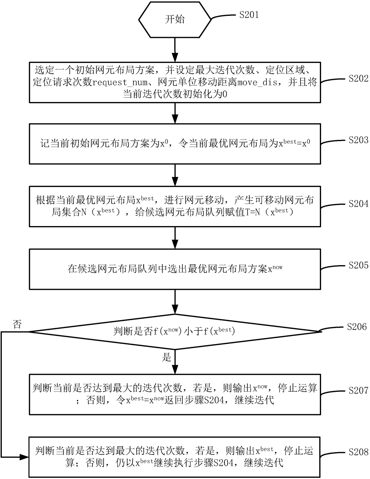
[0069] In this application example, the area to be positioned consists of a room, and the positioning area is a length*width*height of 1*1*1m 3 The minimum value of the coordinates of the point to be located in the room is (-0.5, -0.5, -0.5), and the maximum value is (0.5,0.5,0.5). 12 network elements are set outside the house. The initial value of each network element The coordinates are (1,0,0.5), (-1,0,0.5), (1,0,1),(-1,0,1). According to the steps of the technical solution of the present invention, the remaining parameters are set, including the maximum number of iterations 100,000 times, the number of positioning requests 10 times, the unit moving distance of the network element is 1 m, etc., and the current iteration number is initialized to 0.

[0070] After performing steps S203 to 208, an optimal network element layout is obtained as:

[0071] (3.81,2.45,1.45),(-0.23,3.24,1.34),(1.63,-1.78,2.64),(2.17,1.52,-8.19),(-1.63,-5.46,7.88)(5.61,-...

Example

[0072] Application example 2:

[0073] In this application example, the area to be located is composed of two-story buildings, and the positioning area of ​​each building is a length*width*height of 10*10*3m 3 The minimum value of the coordinates of the point to be located in the room is (-5,-5,-3) and the maximum value is (5,5,3). 12 network elements are set outside the house. The initial value of each network element The coordinates are (5,0,2), (-5,0,2), (5,0,4),(-5,0,4). According to the steps of the technical solution of the present invention, the remaining parameters are set, including the maximum number of iterations 100,000 times, the number of positioning requests 600 times, the unit moving distance of the network element is 1 m, etc., and the current iteration number is initialized to 0.

[0074] After performing steps S203 to 208, an optimal network element layout is obtained as:

[0075] (-8.51,5.46,-8.79), (4.96,7.85,1.23),(2.19,-8.52,1.34),(9.65,2.15,-4.56),

[0076...


PUM


Abstract

The invention discloses an intelligent optimization method and an intelligent optimization device of positioning network element layout, and the method comprises the following steps: according to a set network element moving mode, moving each network element in the current optimal network element layout x<best> of the current iteration, and obtaining a candidate network element layout set; from the candidate network element layout set, selecting an optimal network element layout x<now> of the set; determining a better network element layout from the x<now> and the x<best>, taking the determined network element layout as the current optimal network element layout x<best> of next iteration, and performing iterative processing; when an iteration suspending condition is satisfied, outputting the network element layout determined by the last iteration. With the method and the device provided by the scheme of the invention, a network element layout global optimization process is accelerated,staying at a local optimal solution is avoided, and services based on position information are supported.

Description

technical field [0001] The present invention relates to the technical field of wireless communication, in particular to an intelligent optimization method and device for positioning network element layout. Background technique [0002] A positioning network element refers to a device capable of transmitting and receiving positioning signals, such as a base station, a pseudo base station, and the like. The existing network element layout technology is generally only for large-scale outdoor base station equipment or nodes in wireless sensor networks. The main purpose is to improve communication quality and user service quality, and it can also be used for positioning in theory. The existing network element layout optimization algorithm mainly considers the influence of the position and number of network elements on the overall network coverage and signal quality. Optimal combination, currently there is no network element layout optimization method specifically for indoor 3D p...

Claims


Application Information

Patent Timeline
IPC IPC(8): H04W16/18
CPCH04W16/18
Inventor 陈诗军胡海婧陈强王慧强王园园陈大伟吕宏武
Owner ZTE CORP
Why Eureka
Try Eureka