Heat dissipating device for variable frequency motor

A heat dissipation device and variable frequency motor technology, which is applied in the direction of electromechanical devices, cooling/ventilation devices, electrical components, etc., can solve problems such as processing difficulties, and achieve the effect of simple blade installation and convenient hole formation

Inactive Publication Date: 2016-04-27
泰信电机(苏州)有限公司
View PDF4 Cites 0 Cited by
  • Summary
  • Abstract
  • Description
  • Claims
  • Application Information

AI Technical Summary

Problems solved by technology

The blade is formed by rolling to one side when the impeller punches the air hole, which causes the disadvantage of difficult processing

Method used


Image

  • Heat dissipating device for variable frequency motor
  • Heat dissipating device for variable frequency motor

Examples


Embodiment

[0015] Embodiment: A cooling device for variable frequency motor

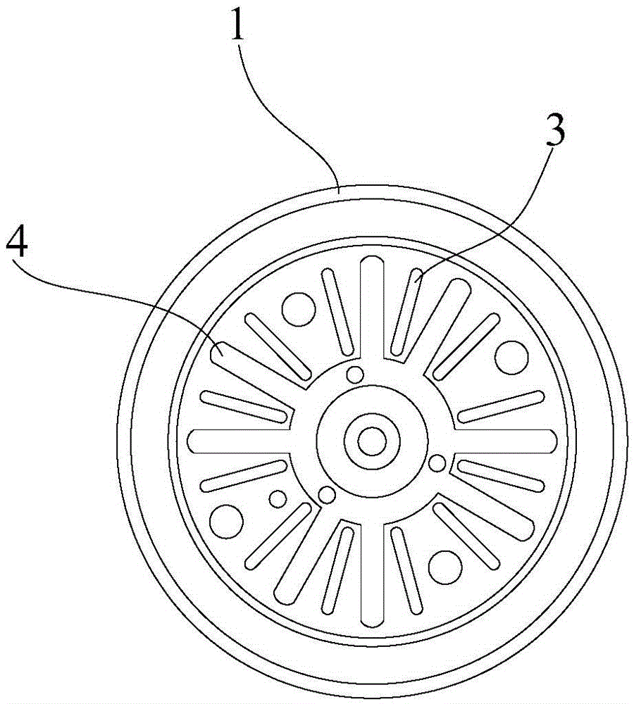
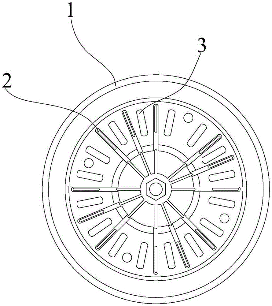
[0016] See attached figure 1 And attached figure 2 As shown, a cooling device for a variable frequency motor includes an impeller 1 whose edge is turned out to one side, a first installation hole is arranged in the center of the impeller 1, and several second installation holes are arranged around the first installation hole , the bottom of the impeller 1 is punched with a plurality of blade installation holes 4 , and a ventilation hole 3 is arranged between two adjacent blade installation holes 4 ; heat dissipation blades 2 are fixed in the blade installation holes 4 . The heat dissipation fins 2 are made of polymer materials.


PUM


Abstract

The invention provides a heat dissipating device for a variable frequency motor. The heat dissipating device comprises an impeller with an edge overturned towards one side, a first mounting hole is formed in the center of the impeller, a plurality of second mounting holes are formed around the first mounting hole, a plurality of blade mounting holes are punched in the bottom of the impeller, and a vent hole is formed between two adjacent blade mounting holes; and heat dissipating blades are fixed in the blade mounting holes. The heat dissipating device provided by the invention has the advantages that the blade mounting holes are formed conveniently, and when the blades are mounted, the blades are mounted simply.

Description

technical field [0001] The invention relates to a heat dissipation device, in particular to a heat dissipation device for a variable frequency motor, and belongs to the technical field of motor preparation. Background technique [0002] Electric machinery (commonly known as motor) refers to an electromagnetic device that realizes the conversion or transmission of electric energy according to the law of electromagnetic induction. It is represented by the letter M (D in the old standard) in the circuit. Generally speaking, a motor is a machine that converts electrical energy into kinetic energy. Such a motor can be divided into a rotary motor that converts electrical energy into rotary motion and a reciprocating motor that converts electrical energy into linear reciprocating motion. Electric motors are installed as power sources in almost all products used in households such as refrigerators, air conditioners, washing machines, electric fans, and vacuum cleaners. [0003] Th...

Claims


Application Information

Patent Timeline
Patent Type & Authority Applications(China)
IPC IPC(8): H02K9/06
CPCH02K9/06
Inventor 崔云镐
Owner 泰信电机(苏州)有限公司
Why Eureka
Try Eureka