Incense burning apparatus

A guiding device and internal combustion incense technology, applied in the direction of gasification substances, disinfection, etc., can solve the problems of easy mixing, aroma cannot be separated, and it is difficult to burn different types of incense, so as to prevent the contamination of external odors and increase brightness , good effect

Inactive Publication Date: 2016-05-04
SHANGHAI XIANGJI IND CO LTD
View PDF4 Cites 0 Cited by
  • Summary
  • Abstract
  • Description
  • Claims
  • Application Information

AI Technical Summary

Problems solved by technology

When several kinds of incense are burned in one room, the aromas of different smells from various incenses cannot be isolated and easily mixed together, so it is difficult to burn different kinds of incense in the same room.

Method used


Image

  • Incense burning apparatus
  • Incense burning apparatus
  • Incense burning apparatus

Examples


Embodiment 1

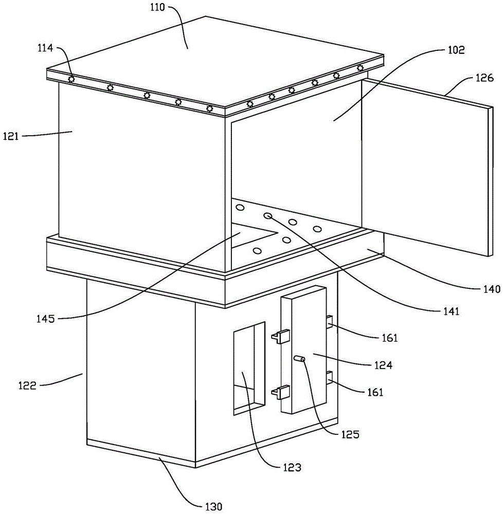
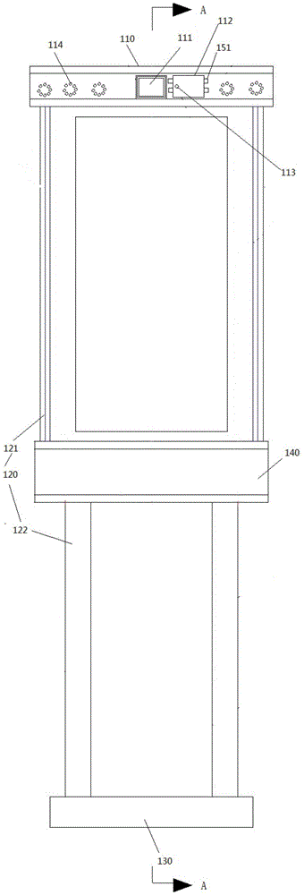
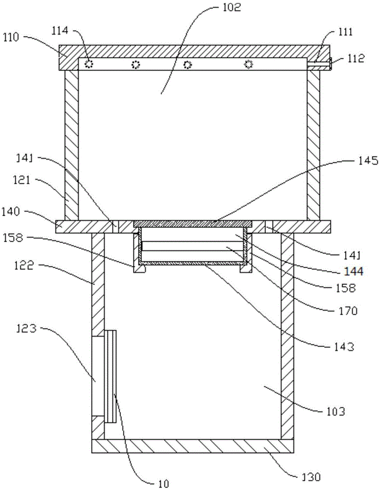
[0042] Such as Figure 1-5 As shown, the incense device includes a box body. The box body includes a box cover 110 , a side wall 120 and a base 130 . The case cover 110 and the base 130 are respectively arranged on the upper end and the lower end of the side wall 120 , and form a cavity with the side wall 120 . The side wall 120 can be an integral structure from top to bottom, or can be assembled from a split structure. The cavities may be of the same size from top to bottom, or may be set with varying sizes. In the embodiment shown in the figure, a partition 140 is provided in the middle of the side wall 120, and the partition 140 divides the side wall 120 into an upper side wall 121 and a lower side wall 122, and at the same time divides the chamber into an upper chamber 102 and a chamber 102. Lower cavity 103. The upper chamber 102 is larger than the lower chamber 103 . The partition 140 is provided with a fourth through hole 141 , and the fourth through hole 141 commu...

Embodiment 2

[0058] Such as Figure 6-8 As shown, the first guiding device in this embodiment is different from that in Embodiment 1, and the first guiding device adopts the first guiding hole 181 . The first guide hole 181 is disposed on the case cover 110 . The first guide hole 181 defines an opening on the inner wall 115 of the first through hole 111 . The first guide hole 181 extends from the first through hole 111 into the box cover 110 . The first barrier 112 is movably inserted in the first guide hole 181 . The first baffle 112 is gradually inserted into the first guide hole 181 along the first guide hole 181 to gradually open the first through hole 111 , and finally fully open the first through hole 111 . When the first through hole 111 is gradually opened, the flow velocity of the aroma flowing out of the cavity through the first through hole 111 is gradually accelerated, and the concentrated aroma in the cavity flows out from the first through hole 111 at a gradually accelerat...

Embodiment 3

[0062] Such as Figure 9 As shown, the first guiding device in this embodiment is different from that in Embodiment 1, and the first guiding device is two opposite first guiding grooves 155 . A groove 156 is disposed on the case cover 110 , and the first through hole 111 is located at the bottom of the groove 156 . The two first guide grooves 155 are respectively arranged on the upper groove wall 157 and the lower groove wall 158 of the groove 156 . The upper and lower ends of the first baffle plate 112 are respectively embedded in the two first guide grooves 155 and arranged to be movable along the first guide grooves 155 .

[0063] The second guiding device can also be implemented with reference to the structure of the first guiding device in this embodiment.

[0064] Except for the above-mentioned structure, other structures of the incense device of this embodiment are the same as those of the incense device of Embodiment 1.


PUM


Abstract

The invention discloses an incense burning apparatus, and is characterized in that: the apparatus comprises a casing; the casing comprises a case cover, sidewalls and a base; the case cover and the base are respectively arranged at the upper end of the sidewalls and the lower end of the sidewalls, and enclose an accommodating chamber with the sidewalls; the accommodating chamber is used for accommodating burned incense; the casing is opened with a first through hole; the first through hole is used for communicating the accommodating chamber with the area outside the accommodating chamber; fragrance generated from the burned incense in the accommodating chamber flows out of the accommodating chamber from the first through hole; the casing is also provided with a second through hole; the first through hole is higher than the second through hole; the second through hole is used for communicating the accommodating chamber with the area outside the accommodating chamber; gas outside the accommodating chamber enters the accommodating chamber from the second through hole, and the gas which carries the fragrance generated from the burned incense in the accommodating chamber flows out of the accommodating chamber from the first through hole. The incense is placed in the accommodating chamber of the incense burning apparatus, and fragrance generated from the burned incense concentrates in the accommodating chamber, in order to increase concentration and purity of the fragrance.

Description

technical field [0001] The invention relates to an incense device. Background technique [0002] Incense was widely used in people's life in ancient China. From smoking, hanging to painting, drinking, and even being used for timekeeping in a whimsical way, it all reflects the ancient people's understanding of "fragrance" as an overseas product and the ancient people's exquisite life interest. From ancient times to the present, no matter what kind of situation you encounter, as long as you light it in the incense burner, you will naturally be able to maintain a relaxed facial expression and a leisurely and contented look. [0003] Tasting incense was a very popular activity in ancient times, especially in the lives of the aristocracy and literati. Incense has continued to this day, and has also become an essential daily necessities for modern people to maintain their health and cultivate their sentiments. Fragrance has the functions of beautifying the environment, pleasing...

Claims


Application Information

Patent Timeline
Patent Type & Authority Applications(China)
IPC IPC(8): A61L9/03
CPCA61L9/032
Inventor 李昆霖
Owner SHANGHAI XIANGJI IND CO LTD
Why Eureka
Try Eureka