Punch

A technology of punches and dies, applied in metal processing equipment, forming tools, manufacturing tools, etc., can solve problems such as single structure of punches, increased production costs of enterprises, and easy damage, so as to improve economic benefits, good buffering effect, The effect of reducing production costs

Inactive Publication Date: 2016-05-04
余姚市震达精工机械有限公司
View PDF0 Cites 2 Cited by
  • Summary
  • Abstract
  • Description
  • Claims
  • Application Information

AI Technical Summary

Problems solved by technology

The current punch is for direct punching without cushioning function, and there is no slope on the end face of the punch. After punching, the edge of the product is prone to burrs, which affects the quality of the product. At the same time, the structural strength of the punch is low and easy to damage, which increases the production of the enterprise. In addition, the single structure of the current punch cannot meet the needs of stamping products of different specifications

Method used


Image

  • Punch
  • Punch

Examples


Embodiment Construction

[0009] The present invention will be further described in detail below in conjunction with the accompanying drawings and specific embodiments.

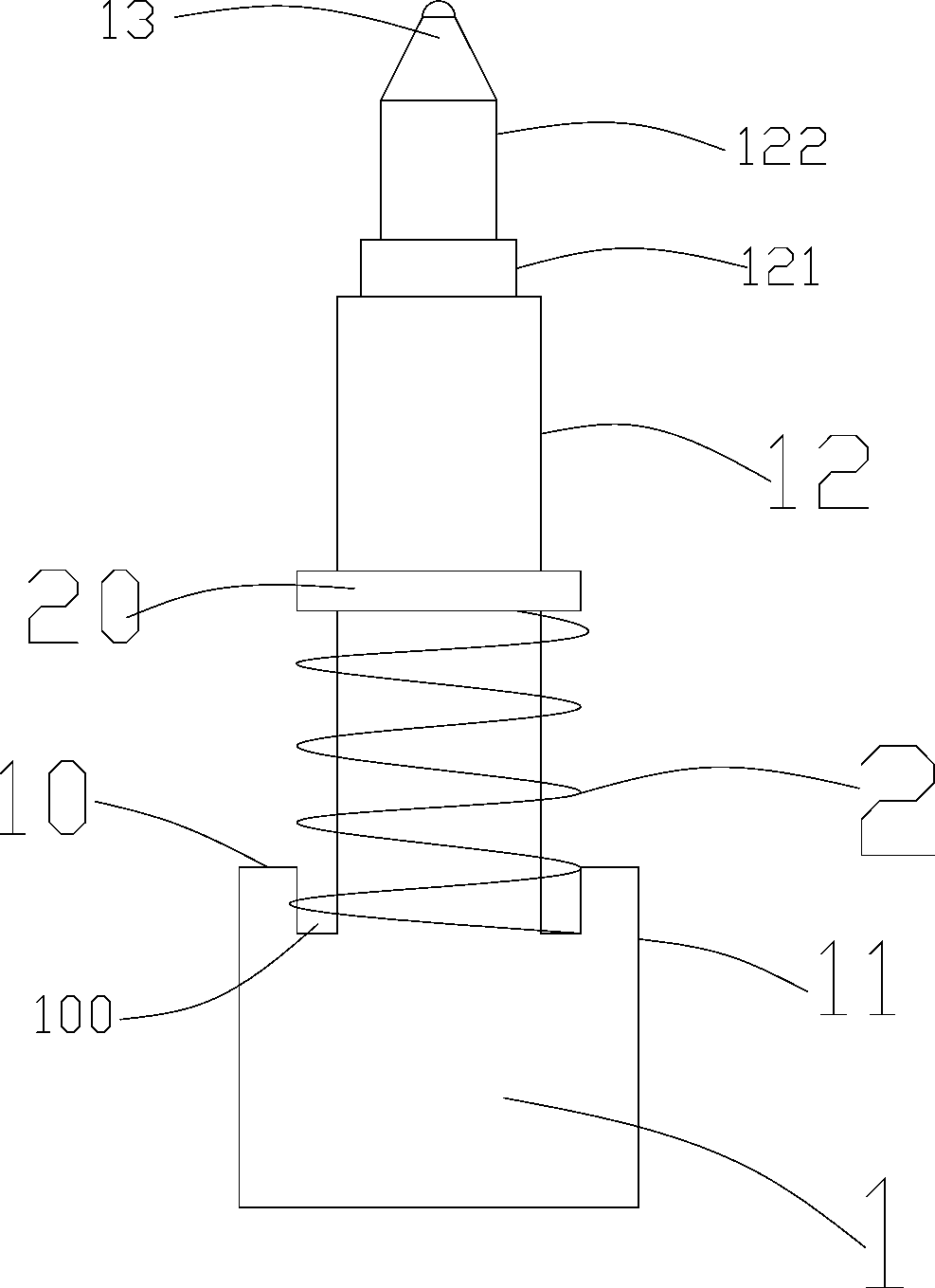
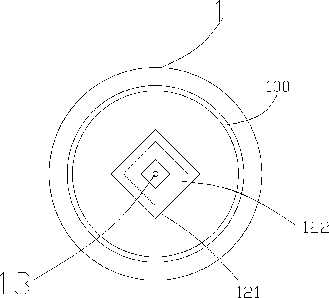
[0010] see figure 1 with figure 2 Shown, a specific embodiment of the punch of the present invention. A punch, including a punch body 1, the punch body 1 is a cylindrical structure, the middle and rear part of the punch body 1 divides the punch body 1 into a front section 11 of the punch and a rear section of the punch through a step 10 Section 12, the step 10 is provided with an annular groove 100, a spring 2 is arranged in the groove 100, the spring 2 is sleeved on the front section 11 of the punch, and the upper part of the spring 2 is provided with an end Cover 20. Arranged like this, since the groove on the punch body is provided with a spring, it can play a good buffering effect, and the spring will not shift.

[0011] Further, a first square die 121 and a second square die 122 are arranged on the front section 11 of the pu...


PUM


Abstract

The invention discloses a punch and belongs to the technical field of punching. The punch comprises a punch body of a cylindrical structure; the middle rear portion of the punch body is divided into a punch front section and a punch rear section through a step; an annular groove is formed in the step; a spring is arranged inside the groove; the punch front section is sleeved with the spring; an end cover is arranged on the upper portion of the spring. Compared with the prior art, as the spring is arranged on the groove in the punch body, a better buffering function can be achieved, and the spring does not shift; the punch structure is not simplex, punching of products of various specifications can be met, the actual production needs are met, the production cost of enterprises is reduced, and economic benefits are improved greatly.

Description

technical field [0001] The invention belongs to the technical field of punching, and in particular relates to a punch. Background technique [0002] The punch is a metal part installed on the stamping die, which is used in direct contact with the material to deform and cut the material. The current punch is for direct punching without cushioning function, and the end face of the punch has no bevel, burrs are prone to appear on the edge of the product after punching, which affects the quality of the product. cost, and the single structure of the current punch cannot meet the needs of stamping products of different specifications. The above problems need to be solved urgently. Contents of the invention [0003] The invention provides a punch aiming at the deficiencies in the prior art. [0004] In order to solve the above technical problems, the present invention is solved by the following technical solutions: a punch, including a punch body, the punch body is a cylindric...

Claims


Application Information

Patent Timeline
Patent Type & Authority Applications(China)
IPC IPC(8): B21D37/10B21D37/12
CPCB21D37/10B21D37/12
Inventor 宋余斌
Owner 余姚市震达精工机械有限公司
Why Eureka
Try Eureka