Wire bending device

A bending device and wire technology, applied in the field of wire processing, can solve problems such as affecting plug assembly, low efficiency, and difficulty in ensuring cable alignment, and achieve the effect of improving efficiency

Inactive Publication Date: 2016-05-04
DONGGUAN SENJIA MACHINERY
View PDF8 Cites 20 Cited by
  • Summary
  • Abstract
  • Description
  • Claims
  • Application Information

AI Technical Summary

Problems solved by technology

[0002] At this stage, when assembling the plug at the end of the cable, the coiled wire is pulled into a straight line, and then the fixed length of the wire is cut by a cutting mechanism, and then the wire is moved horizontally, and the plug is installed at the end of the wire; Some products need to assemble plugs at both ends of the cable, and correspondingly set up two assembly stations on the subsequent assembly equipment to match the assembly of the two plugs. In this way, the cable must be bent after the cable is cut. Fold to put the two ends of the cable on the same side, and then traverse to enter the plug installation station. In the existing equipment, after the cable is cut, the cable is manually bent and then sent to the traverse mechanism; The efficiency of manual operation is low, and it is difficult to ensure that the two ends of the cable are aligned, which affects the subsequent assembly of the plug

Method used


Image

  • Wire bending device
  • Wire bending device

Examples


Embodiment Construction

[0023] Below, in conjunction with accompanying drawing and specific embodiment, the present invention is described further:

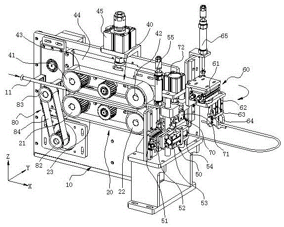
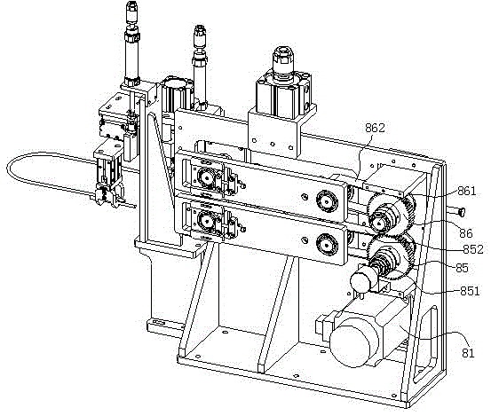
[0024] Such as figure 1 , 2 As shown, it is a wire bending device of the present invention, which includes a frame 10, a first belt conveying assembly 20, a second belt conveying assembly 40, a driving assembly 80, a wire bending assembly 60, a wire clamping assembly 50, a cutter Cut assembly 70.

[0025] Wherein the frame 10 is used as the installation base of the whole device, and the first belt conveying assembly 20 is installed on the frame 10, specifically, the first belt conveying assembly 20 includes a first driving pulley 21 pivotally connected on the frame 10 , the first driven pulley 22 pivotally connected on the frame 10, the first drive belt 23 that is wound around the first drive pulley 21 and the first driven pulley 22 outside synchronously, the first drive belt 23 Extend along the length direction of the rack 10 (that is, the X directi...


PUM


Abstract

The invention discloses a wire bending device. The wire bending device comprises a frame; a first belt conveying component; a vertical plate; a second belt conveying component opposite to a first conveying belt up and down and bonded with the first conveying belt to form a wire feeding mechanism for clamping and conveying wires; a driving component; a wire bending component including a first air jaw cylinder, two first clamping jaws mounted at a free end of the first air jaw cylinder, a rotating cylinder for driving the first air jaw cylinder to swing between a position on the outer side of the tail end of the wire feeding mechanism and a position far from the tail end of the wire feeding mechanism, and a first lifting cylinder for driving a cylinder body of the rotating cylinder to move in the height direction of the frame; a wire clamping component; and a cutting component. In the wire bending device, the wire bending process is automatically finished, so that the wire bending efficiency is improved; and meanwhile, the wires are cut after being bent to possibly guarantee levelness of two ends of the wires.

Description

technical field [0001] The invention relates to the technical field of wire rod processing, in particular to a wire rod bending device. Background technique [0002] At this stage, when assembling the plug at the end of the cable, the coiled wire is pulled into a straight line, and then the fixed length of the wire is cut by a cutting mechanism, and then the wire is moved horizontally, and the plug is installed at the end of the wire; Some products need to assemble plugs at both ends of the cable, and correspondingly set up two assembly stations on the subsequent assembly equipment to match the assembly of the two plugs. In this way, the cable must be bent after the cable is cut. Fold to put the two ends of the cable on the same side, and then traverse to enter the plug installation station. In the existing equipment, after the cable is cut, the cable is manually bent and then sent to the traverse mechanism; The efficiency of manual operation is low, and it is difficult to ...

Claims


Application Information

Patent Timeline
Patent Type & Authority Applications(China)
IPC IPC(8): B21F1/00
CPCB21F1/00
Inventor 甘宝连
Owner DONGGUAN SENJIA MACHINERY
Why Eureka
Try Eureka