[0023] The technical solutions in the embodiments of the present invention will be clearly and completely described below in conjunction with the accompanying drawings in the embodiments of the present invention. Obviously, the described embodiments are only a part of the embodiments of the present invention, rather than all the embodiments. Based on the embodiments of the present invention, all other embodiments obtained by those of ordinary skill in the art without creative work shall fall within the protection scope of the present invention.
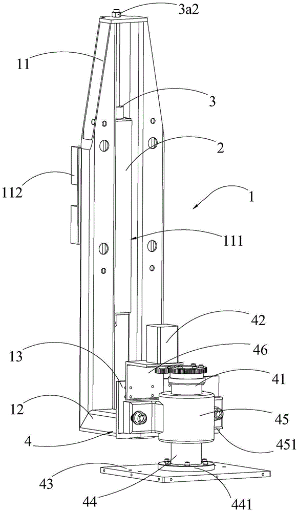
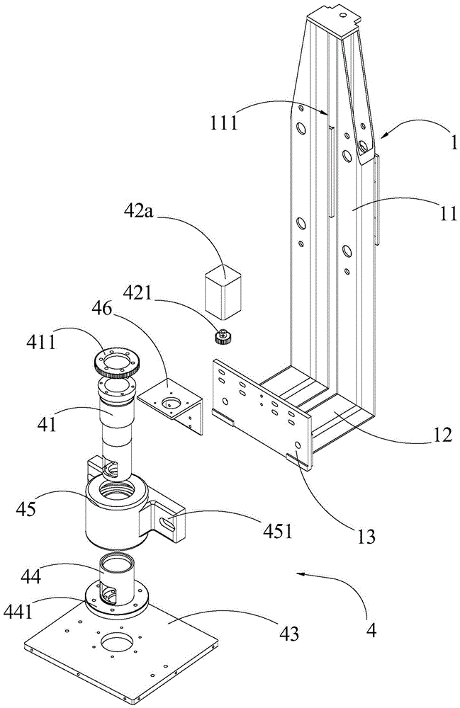
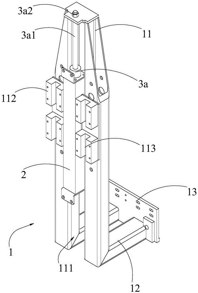
[0024] See figure 1 , The embodiment of the present invention provides an adjustment device for a marking machine, which is applied to a marking machine, and includes a bracket 1, a mounting seat 2, a telescopic rod 3, and a rotating mechanism 4. The mounting seat 2 is mainly used for connecting with peripherals. The torch box (not shown in the figure) is fixedly connected, and the telescopic rod 3 can be telescopically extended along its length. One end is fixedly connected to the mounting base 2 and the other end is fixedly connected to the bracket 1, and the whole is vertically arranged. The rotating mechanism 4 is installed on the bracket 1, and the structure of the rotating mechanism 4 is refined. It includes a rotating shaft 41 and a driving member 42. The rotating shaft 41 is vertically installed on the bracket 1. The rotating shaft can be driven by the driving member 42. 41 rotates horizontally around its own axis. Generally, an adapter plate 43 is fixed at one end of the rotating shaft 41, and the adapter plate 43 is mainly used to install a marking head for peripherals (not shown in the figure). In this embodiment, by adjusting the telescopic rod 3 to expand and contract in the vertical direction, the bracket 1 can be driven to rise or fall in the vertical direction relative to the mounting seat 2 or the torch box. When the marking head is installed on the adapter plate 43 When up, the marking head moves in the vertical direction. On the other hand, the driving member 42 can be controlled to work, and the driving member 42 drives the rotating shaft 41 to drive the adapter plate 43 to rotate in the horizontal direction around the axis of the rotating shaft 41. , And it also realizes the angle adjustment of the marking head in the horizontal direction. For this, the position of the marking head can be adjusted by flexibly controlling the telescopic rod 3 and the driving part 42 to meet the marking actions of various positions and angles. , The work is more convenient, and in the above-mentioned work process, the telescopic rod 3 and the driving member 42 can be accurately controlled, and the consistency of the products after marking is very high.
[0025] See figure 1 as well as figure 2 Optimize the structure of the bracket 1. The bracket 1 has a guide groove 111 arranged in the vertical direction. The telescopic rod 3 and the mounting seat 2 are located in the guide groove 111, and the upper end of the telescopic rod 3 is connected to the top of the guide groove 111, and the lower end Fixedly connected with the mounting base 2. In application, the adjustment device is integrally fixed to the torch box through the mounting base 2, which is the fulcrum after the adjustment device is fixed, and then supports the bracket 1, the rotating mechanism 4 and the mounting on the adapter plate 43 through the telescopic rod 3 In the marking head, under normal circumstances, the telescopic rod 3 is in a contracted state, and there is no need to overcome the gravity of the bracket 1 to do work. In the working state, the telescopic rod 3 is extended. At this time, the gravity of the bracket 1 and the like can be used with the telescopic rod. 3 The shrinking force can offset the longitudinal reaction force generated when the marking head is working, making the marking head more stable and longer service life. In addition, the mounting seat 2 and the telescopic rod 3 are located in the guide groove 111, which can improve the stability of the structure .
[0026] Optimizing the foregoing embodiment, the bracket 1 is further provided with at least one sliding block 112 on both sides of the guide groove 111, and each sliding block 112 is in a sliding connection with the guide rail of the torch box. In this embodiment, there are two sliding rails on the torch box, and they are both arranged in a vertical direction, and the bracket 1 is provided with at least one sliding block 112 on each side of the guide groove 111, usually 2-3 blocks. Each sliding block 112 is provided with a sliding groove 113, and the sliding grooves 113 on each sliding block 112 on each side are located on the same vertical line. When the torch box is fixedly connected to the mounting base 2, the torch box The two sliding rails are located in the sliding grooves 113 on both sides of the bracket 1, and the telescopic rod 3 is extended or contracted. Each sliding rail slides relatively along the corresponding sliding grooves 113, which can further enhance the vertical movement of the bracket 1 The stability can effectively avoid shaking during the movement.
[0027] See figure 1 as well as image 3 , To refine the driving mode between the rotating shaft 41 and the driving part 42, a transmission gear 411 is sleeved on the rotating shaft 41, and the driving part 42 can be a motor 42a, usually a stepping motor 42a, on the output shaft of the motor 42a Another driving gear 421 is provided thereon, and the driving gear 411 on the rotating shaft 41 is in meshing connection with the driving gear 421 on the output shaft of the motor 42a. In this embodiment, the stepping motor 42a and the rotating shaft 41 are both mounted on the bracket 1. When the stepping motor 42a works, its output shaft drives the driving gear 421 to rotate, and the driving gear 421 drives the transmission gear 411 meshed with it to rotate. The transmission gear 411 drives the rotating shaft 41 and the adapter plate 43 to rotate synchronously. In the above transmission path, the stepping motor 42a and the rotating shaft 41 are geared, which is not only more convenient to control, but also has very high accuracy. In addition, the gear transmission transmits greater torque, which is more conducive to the installation of steel at the adapter plate 43. Needle marking head. Generally, the rotating mechanism 4 also includes a sleeve 44, which is arranged vertically, and one end is fixedly connected to the adapter plate 43, and the other end is connected to the rotating shaft 41 through a ball bearing 45. The ball bearing 45 has a mounting To the stand 451 on the support 1. The lower end of the sleeve 44 has a flange 441, which is connected and fixed by bolts with the adapter plate 43. The upper end of the flange 441 and the lower end of the rotating shaft 41 respectively extend into the ball bearing 45. The ball bearing 45 makes the sleeve 44 rotates synchronously with the rotating shaft 41, and the ball bearing 45 is fixed on the support 1 through the stand 451, which can effectively limit the longitudinal movement of the rotating shaft 41 and the sleeve 44 when rotating synchronously.
[0028] See Figure 1-Figure 3 , The structure of the support 1 is refined. The support 1 includes a guide plate 11 and a connecting plate 12. The guide plate 11 is arranged vertically, and the connecting plate 12 is arranged horizontally and installed at the lower end of the guide plate 11. For this reason, the guide plate 11 and the connecting plate 12 The combination has an L-shaped structure, the telescopic rod 3 is fixed on the guide plate 11, and the driving member 42 is installed at the connecting plate 12. Specifically, the guide groove 111 is located on the guide plate 11, that is, the upper end of the telescopic rod 3 is connected to the guide plate 11, and after it is stretched, it abuts the upper end of the guide plate 11, and each slider 112 is also arranged on the guide plate 11 facing the cutting torch. On one side of the box, the guide plate 11 slides up and down relative to the torch box under the action of the telescopic rod 3. In addition, the connecting plate 12 is located at the lower end of the guide plate 11, and the rotating mechanism 4 is installed at the connecting plate 12, which means that the rotating mechanism 4 is far away from the telescopic rod 3 against the guide plate 11, which can improve the rotation of the telescopic rod 3 when it is working. Stability of organization 4. The structure of the guide plate 11 is optimized, the upper end of the guide plate 11 is tapered, and the telescopic rod 3 abuts to the upper end of the guide plate 11. The extension of the telescopic rod 3 requires a certain force to be exerted on the upper end of the guide plate 11. The upper end of the guide plate 11 is tapered and shrinks along the extension direction of the telescopic rod 3, which can increase the upper end of the guide plate 11. The strength of the structure is adapted to the force generated by the telescopic rod 3. For the telescopic rod 3, a lifting cylinder 3a is usually used, and the cylinder body is fixedly connected to the mounting base 2, and the telescopic shaft 3a1 and the bracket 1 are fixedly connected by a nut 3a2, specifically the end of the telescopic shaft 3a1 away from the cylinder body It has an external thread that passes through the upper end of the guide plate 11, and then uses a nut 3a2 to lock the upper end of the telescopic shaft 3a1, thereby forming a fixed connection between the telescopic rod 3 and the guide plate 11. Compared with the ball screw structure, the lifting cylinder 3a greatly saves costs, and can be more perfectly applied to a steel needle marking system with only two working positions, and the telescopic control is relatively simple.
[0029] Further, the bracket 1 further includes a mounting plate 13, which is also vertically arranged, the two ends of the connecting plate 12 are respectively connected to the mounting plate 13 and the guide plate 11, and the rotating shaft 41 and the driving member 42 are both mounted on the mounting plate 13. on. In this embodiment, the extension direction of the mounting plate 13 is the same as the extension direction of the guide plate 11. The stand 451 of the ball bearing 45 is fixed to the mounting plate 13 by bolts, and the motor 42a is also fixed to the mounting plate through a motor mounting plate 46. On board 13. In addition, since the mounting plate 13, the connecting plate 12 and the guide plate 11 are enclosed and formed with a U-shaped groove, in another installation method, the motor 42a and the motor mounting plate 46 can be installed in the U-shaped groove, and the mounting plate 13 Only the stand 451 of the ball bearing 45 is fixed on it.
[0030] See again figure 1 The embodiment of the present invention also provides a steel needle marking machine, which includes a torch box, a marking head, and the aforementioned adjustment device. The torch box is fixed to the mounting base 2, and the marking head is mounted on the adapter plate 43. In this embodiment, the adjustment device is used in conjunction with the torch box and the marking head, and the position of the marking head can be flexibly adjusted according to different raw materials. Not only is the structure simple, but it can also be accurately controlled, and the marking position of the raw material is consistent. high.
[0031] The above descriptions are only preferred embodiments of the present invention and are not intended to limit the present invention. Any modification, equivalent replacement, improvement, etc. made within the spirit and principle of the present invention shall be included in the present invention. Within the scope of protection.