Buffering device where permanent magnet is utilized

A buffer device and permanent magnet technology, applied in the direction of bumpers, etc., to achieve good protection effect and safety performance guarantee effect

Inactive Publication Date: 2016-05-04
孙莉新
View PDF9 Cites 1 Cited by
  • Summary
  • Abstract
  • Description
  • Claims
  • Application Information

AI Technical Summary

Problems solved by technology

However, such systems require complex sensors and electromechanical systems to function, and their reliability performance is still questionable
Most importantly, it still does not solve the problem of how to effectively provide protection when the inevitable collision occurs

Method used


Image

  • Buffering device where permanent magnet is utilized
  • Buffering device where permanent magnet is utilized
  • Buffering device where permanent magnet is utilized

Examples


Embodiment 1

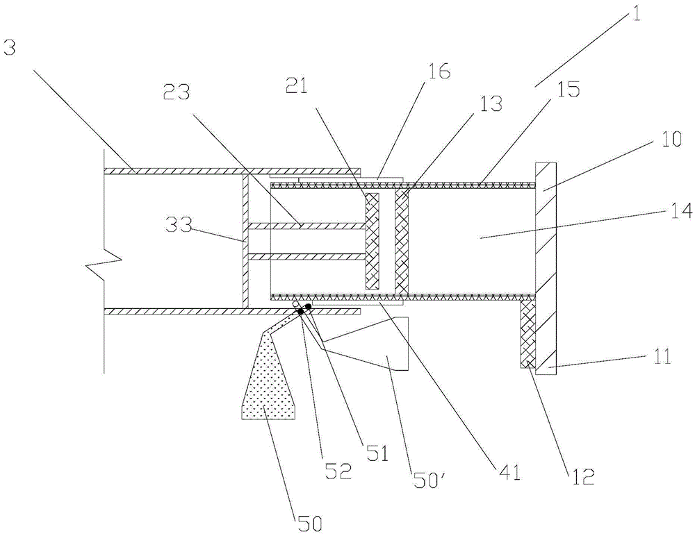
[0038] Such as figure 1 As shown, the present invention shows a buffer device 1, which is particularly suitable for use in front and rear bumpers of automobiles or vehicles. The buffer device 1 includes a bumper cross bar 10 that is attached to the frame 3 through a bumper connector 15 and can move relative to the longitudinal direction of the frame 3 (ie, the longitudinal direction of the vehicle). Of course, this embodiment does not exclude that the bumper bar 3 is also attached to the frame 3 by other means at the same time.

[0039] In a typical vehicle, the bumper crossbar 10 is mounted on the longitudinal beams of the two frame, through a rail 16 ball bearing or similar device installed between the longitudinal beam of the frame and the bumper connector (not shown in the figure) Out) realize the longitudinal movement of the bumper bar, which is well known in the automotive field, and will not be repeated here.

[0040] The bumper connecting piece 15 is a hollow tubular piece...

Embodiment 2

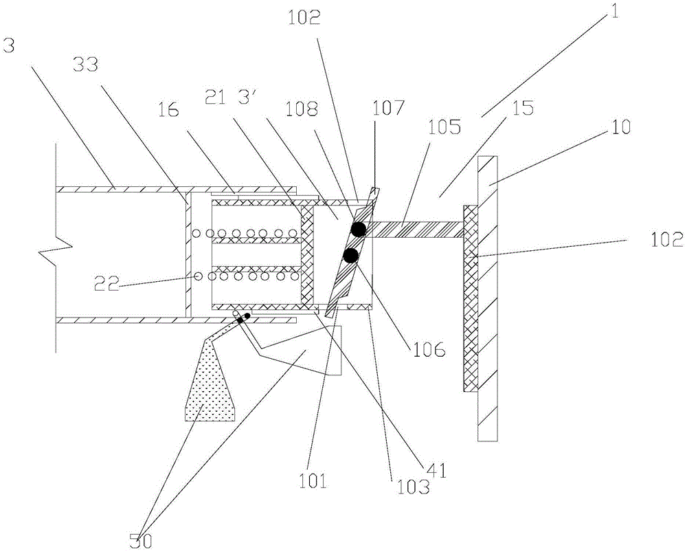
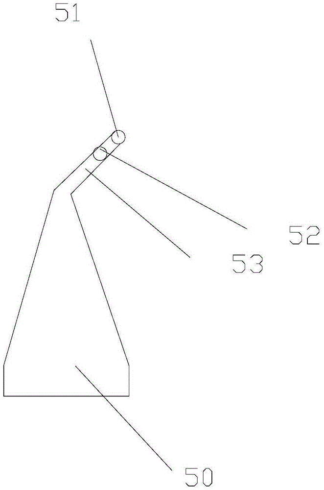
[0047] On the basis of Example 1, such as figure 1 with 3 As shown, the lower side wall of the frame 3 has a groove, which is suitable for allowing the long cantilever 53 of the pendulum 51 to pass through the groove, and to be rotatably attached to the lower part of the frame 3 through a pin 52. Side wall.

[0048] The position of the lower side wall of the bumper connector 15 corresponding to the groove is provided with a stopper 41. When the bumper connector 15 moves in the longitudinal direction of the frame 3, the stopper 41 will come from the bumper bar 10 The impact force is transmitted to the driving end 51 at the end of the long cantilever 53 of the pendulum 51, so that the pendulum swings against the action of gravity. Since the long cantilever 51 rotates around the pin shaft 52, and the distance between the drive end 51 and the pin shaft 52 is much smaller than the distance from the center of gravity of the pendulum 50 to the pin shaft, according to the principles of m...


PUM


Abstract

The invention discloses a buffering device (1). The buffering device comprises a bumper cross rod (10) which is attached and connected to a frame (3) through a bumper connection piece (15) and can longitudinally move relative to the longitudinal direction of the frame (3). The buffering device is characterized in that the lower side wall of the frame (3) is provided with a groove; the groove is suitable for a long cantilever (53) of a pendulum bob (51) to pass, and the long cantilever (53) of the pendulum bob (51) is attached and connected to the lower side wall of the frame (3) through a pin shaft (52) in a free rotating mode; a blocking piece (41) transmits impacting force from the bumper cross rod (10) to a driving end (51) at the end of the long cantilever (53) of the pendulum bob (51) so that the pendulum bob can generate swing overcoming the gravity action. Due to the fact that the long cantilever rotates around the pin shaft, the distance between the driving end and the pin shaft is smaller than the distance from the gravity center of the pendulum bob to the pin shaft, and the pendulum bob can generate large reactive force according to the mechanics principle.

Description

Technical field [0001] The invention relates to a buffer device, in particular to a buffer device using permanent magnets for vehicle bumpers. Background technique [0002] Generally, bumpers are installed on cars or other vehicles, so that when the car collides with cars or other obstacles, the bumpers installed at the front and rear of the car absorb and buffer the external impact and protect the safety of the front and rear parts of the body. Reduce the damage to personnel and vehicles during high-speed impact. Generally speaking, by setting a buffer material between the bumper and the body, when the bumper is impacted, the impact force is transferred to the body, so that the buffer material is deformed during the interaction between the bumper and the body. Absorption and cushioning effect. [0003] For example, a Chinese patent CN104742838A discloses an automobile bumper, which includes a body and a bumper mounted on the body. The bumper acts as a buffer during a collision. ...

Claims


Application Information

Patent Timeline
IPC IPC(8): B60R19/24B60R19/40
CPCB60R19/24B60R19/40
Inventor 孙莉新
Owner 孙莉新
Why Eureka
Try Eureka