Digital infrared temperature sensor
An infrared temperature and temperature sensor technology, which is applied in the direction of railway vehicle shape measuring devices, electric radiation detectors, and sensing the radiation of moving objects, can solve the problems of inability to achieve data integration, inflexible system design, and poor anti-interference performance of analog signals And other problems, to achieve the effect of flexible system design, improve reliability, and prevent signal distortion
- Summary
- Abstract
- Description
- Claims
- Application Information
AI Technical Summary
Problems solved by technology
Method used
Image
Examples
Embodiment 1
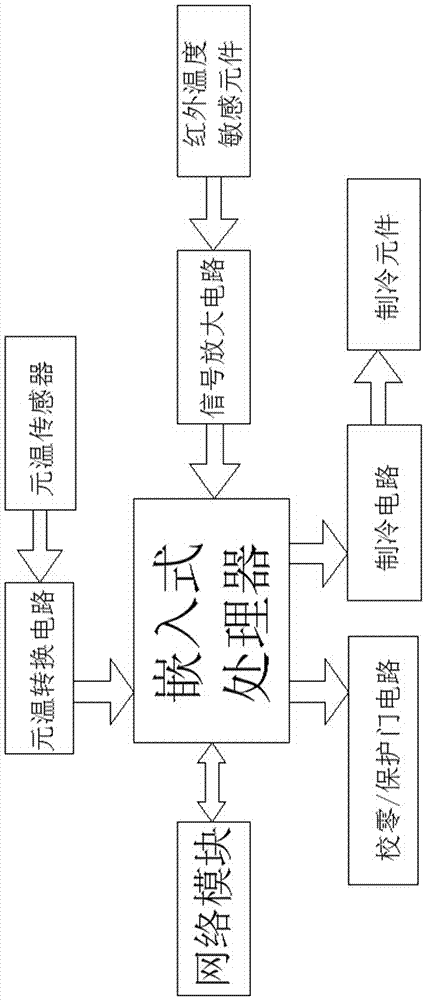
[0037] combine figure 1 Description, a digital infrared temperature sensor, its composition includes: an infrared temperature sensitive element, an embedded processor, an element temperature sensor, a refrigeration circuit, a network module, the infrared temperature sensitive element transmits a signal to the signal amplification circuit in one direction, and the The signal amplification circuit unidirectionally transmits signals to the embedded processor, the element temperature sensor unidirectionally transmits signals to the element temperature conversion circuit, and the element temperature conversion circuit unidirectionally transmits signals to the embedded processor. processor, the embedded processor unidirectionally transmits signals to the zero calibration / protection gate circuit, the embedded processor unidirectionally transmits signals to the refrigeration circuit, and the refrigeration circuit unidirectionally transmits signals to the refrigeration element, so The ...
Embodiment 2
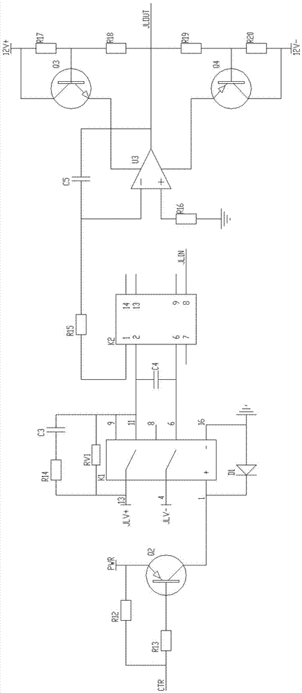
[0039] combine figure 2 To illustrate, in the digital infrared temperature sensor described in Embodiment 1, the element temperature conversion circuit receives the signal of the element temperature sensor to one end of the resistor R2, one end of the variable resistor RW1, one end of the resistor R3 and the capacitor C1. One end, the resistor R2 is connected in parallel with pin No. 1 of the chip U1, pin No. 2 of the chip U1 and one end of the resistor R1, and the other end of the resistor R1 is connected to the other end of the variable resistor RW1 At one end, the pin No. 6 of the chip U1 is connected in parallel with the other end of the resistor R3 and the other end of the capacitor C1;
[0040] Pin No. 3 of the chip U1 is connected in parallel with one end of the variable resistor RW2 and one end of the resistor R4, the other end of the variable resistor RW2 is connected to one end of the resistor R5, and the other end of the resistor R5 is connected to the The pin num...
Embodiment 3
[0047] combine Figure 4 Illustrate, the digitized infrared temperature sensor described in embodiment 1, described signal amplifying circuit undertakes the signal of described infrared temperature sensitive element to the inverting input terminal of U4 of operational amplifier and one end of resistance R21, described operational amplifier One end of the resistor R24 and one end of the resistor R22 are connected in parallel to the positive phase input end of U4, the other end of the resistor R24 is connected to one end of the resistor R25, the other end of the resistor R25 is grounded, and the other end of the resistor R22 The other end of the resistor R21 is connected in parallel with one end of the resistor R23, and the other end of the resistor R23 is grounded;
[0048] The output terminal of U4 of the operational amplifier is connected to one end of the resistor R26, and the other end of the resistor R26 is connected in parallel with one end of the resistor R28, one en...
PUM
 Abstract
Description
Claims
Application Information
 - R&D
- Intellectual Property
- Life Sciences
- Materials
- Tech Scout
- Unparalleled Data Quality
- Higher Quality Content
- 60% Fewer Hallucinations
Browse by: Latest US Patents, China's latest patents, Technical Efficacy Thesaurus, Application Domain, Technology Topic, Popular Technical Reports.
© 2025 PatSnap. All rights reserved.Legal|Privacy policy|Modern Slavery Act Transparency Statement|Sitemap|About US| Contact US: help@patsnap.com


