
Continuous conveying device for crystal precipitation

A transmission device and crystal technology, applied in packaging and other directions, can solve the problems of unfavorable large-scale continuous production and cumbersome obtaining steps, and achieve the effect of improving continuous production capacity

Active Publication Date: 2016-05-04
NINGXIA DONGWU AGROCHEM
View PDF5 Cites 0 Cited by
  • Summary
  • Abstract
  • Description
  • Claims
  • Application Information

AI Technical Summary

Problems solved by technology

[0002] In chemical production, some products are obtained by precipitation and precipitation after solution reaction. To take out the precipitated chemical products, the general method is to filter out after the reaction is completed or to filter through the bottom opening. These obtaining methods are obtained. The steps are cumbersome, which is not conducive to large-scale continuous production

Method used


Image

  • Continuous conveying device for crystal precipitation
  • Continuous conveying device for crystal precipitation

Examples


Embodiment Construction

[0013] Below in conjunction with accompanying drawing and embodiment the present invention is further described:

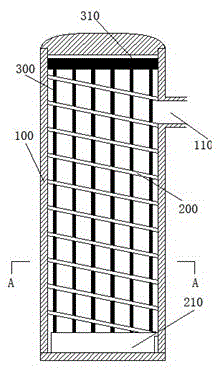
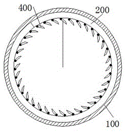
[0014] In this example, see figure 1 and figure 2 , the continuous conveying device for crystallization includes a cylindrical grid 300, a spring-shaped conveying paddle 200 and a cylindrical housing 100, the inner circumference of the conveying paddle 200 and the cylindrical grid 300 The outer circumference of the conveying paddle 200 is adapted to the inner circumference of the cylindrical housing 100, and the cylindrical grid 300, the conveying paddle 200 and the cylindrical housing 100 are sequentially nested to form three Layer nesting structure, one end inside the cylindrical housing 100 is provided with a motor-driven drive end cover 210 , and one end of the delivery paddle 200 is fixed on the drive end cover 210 . One end of the cylindrical housing 100 is provided with a discharge hole 110 matched with the conveying paddle 200 .

[0015] In the above-m...


PUM


Abstract

The invention provides a continuous conveying device for crystal precipitation. The continuous conveying device comprises a grid defining a cylinder, a spring-shaped conveying blade and a cylindrical shell. The inner circumference of the conveying blade is matched with the outer circumference of the cylindrical grid. The outer circumference of the conveying blade is matched with the inner circumference of the cylindrical shell. The cylindrical grid, the conveying blade and the cylindrical shell are sequentially embedded to form a three-layer embedded structure. A driving end cover driven by a motor is arranged at one end in the cylindrical shell, and one end of the conveying blade is fixed to the driving end cover. A discharging hole matched with the conveying blade is formed in one end of the cylindrical shell. In the continuous conveying device, due to rotation of the conveying blade, generated materials are tightly attached to the inner wall of the cylindrical shell due to centrifugal force; and due to the fact that the conveying blade is of a structure similar to a screw extruder, the materials are continuously pushed out of a discharging port, and the continuous production capability is improved.

Description

Technical field [0001] The invention relates to the field of material delivery, in particular to a continuous conveying device for crystallization. Background technique [0002] In chemical production, some products are obtained by precipitation and precipitation after solution reaction. To take out the precipitated chemical products, the general method is to filter out after the reaction is completed or to filter through the bottom opening. These obtaining methods are obtained. The steps are cumbersome and unfavorable for large-scale continuous production. Contents of the invention [0003] In order to solve the above problems, the object of the present invention is to provide a continuous conveying device for crystallization, which can continuously convey the crystals in the reactor. [0004] The technical solution adopted by the present invention to solve its technical problems is: [0005] The continuous conveying device for crystallization includes a cylindrical g...

Claims


Application Information

Patent Timeline
IPC IPC(8): B65G33/12
CPCB65G33/12
Inventor 金伟强
Owner NINGXIA DONGWU AGROCHEM
Learn More