Object lifter structure

A sundry crane and jib technology, applied to cranes and other directions, can solve problems such as bulky and difficult jibs, and achieve the effects of simple operation, improved stability, and simple and convenient disassembly and maintenance

Inactive Publication Date: 2016-05-04
WUXI SHENGOU MARINE EQUIP
View PDF6 Cites 1 Cited by
  • Summary
  • Abstract
  • Description
  • Claims
  • Application Information

AI Technical Summary

Problems solved by technology

The structure of the traditional debris crane is relatively simple. The root of the boom is inserted into the base, the upper end of the base is provided with a flange surface, and the root of the

Method used


Image

  • Object lifter structure
  • Object lifter structure

Examples


Embodiment Construction

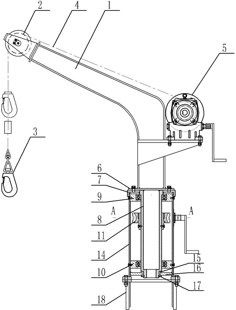
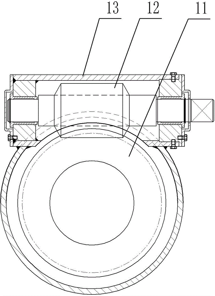
[0012] Such as Figure 1 to Figure 2 As shown, it includes a boom 1, a base 18, a lifting device 5, a pulley 2, a wire rope 4 and a hook group 3, and also includes a connecting rod 8, a worm wheel 11, a worm 12 and a support body 14. The root of the boom 1 is fixed with The connecting rod 8 is fixedly connected with a support body 14 on the base, and the support body is a cylindrical structure with openings at both ends. The connecting rod 8 is inserted into the support body along the axial direction. The bearing seat 10 is fixedly connected, the two ends of the connecting rod 8 are supported on the bearing seat, the worm gear 11 is set on the connecting rod 8, the supporting body is provided with a mounting seat 13, the two ends of the worm 12 are supported on the mounting seat 13, and are connected with the worm wheel 11 Mesh connection, the end of the worm 12 is fixed with a rocker arm; the opening at the lower end of the support body is fixed with a ring-shaped cover plate...


PUM


Abstract

The present invention provides an object lifter structure, wherein the lifting arm can easily rotate so as to achieve lifting of the objects in different orientations. The object lifter structure comprises a lifting arm, a base, a lifting device, a pulley, a steel wire rope and a hanging hook group, and is characterized further comprising a connection rod, a worm wheel, a worm rod and a support body, wherein the root portion of the lifting arm is fixedly connected to the connection rod, the base is fixedly connected to the support body, the support body is a cylindrical structure with openings on both ends, the connection rod is axially inserted inside the support body, the upper end and the lower end of the support body are respectively fixedly connected to a group of bearing pedestals, both ends of the connection rod are supported on the bearing pedestals, the worm wheel is arranged on the connection rod, the support body is provided with an installation seat, both ends of the worm rod are supported on the installation seat and are engaged to the worm wheel, and the end portion of the worm rod is fixedly connected to a rocker arm.

Description

technical field [0001] The invention relates to the technical field of marine lifting equipment, in particular to the structure of a sundries crane. Background technique [0002] There are different types of lifting equipment installed in different areas of the ship. These lifting equipment choose different models and specifications according to the needs of transportation materials, and are collectively called debris cranes. The structure of the traditional debris crane is relatively simple. The root of the boom is inserted into the base, the upper end of the base is provided with a flange surface, and the root of the boom is provided with a locking structure. The fixing of the boom, but the existing boom is very heavy, and it is difficult to manually rotate the boom when lifting materials in different directions. Contents of the invention [0003] In view of the above problems, the present invention provides a sundry hanging structure, which can conveniently rotate the ...

Claims


Application Information

Patent Timeline
IPC IPC(8): B66C23/16
Inventor 张忠胡文骊
Owner WUXI SHENGOU MARINE EQUIP
Why Eureka
Try Eureka