Hydraulic jack for rapidly lifting load

A technology of hydraulic jack and hydraulic oil, applied in the field of hydraulic jack, can solve the problems of large and small pump core resistance, inoperable handle, slow lifting speed, etc., to achieve the effect of fast lifting speed, short time-consuming and high work efficiency

Inactive Publication Date: 2016-05-04
CHANGSHU TONGRUN AUTO ACCESSORY
View PDF8 Cites 0 Cited by
  • Summary
  • Abstract
  • Description
  • Claims
  • Application Information

AI Technical Summary

Problems solved by technology

[0004] When the hydraulic jack is in the load lifting state, in order to facilitate the handle operation, the oil passage connecting the inner chamber of the large pump and the hydraulic oil tank must be opened, otherwise the hydraulic oil in the inner chamber of the large and small pumps will have too much resistance to the pump cores of the large and small pumps. As a result, the handle cannot be operated, the hydraulic oil in the inner chamber of the large pump flows directly into the oil tank, the large pump core is unloaded, and only the small pump core works, the hydraulic oil in the inner cavity of the small pump enters the oil cylinder, and the oil intake is small, pushing The piston rod lifts slowly, and the piston rod pushes the heavy object to lift
[0005] Therefore, when the above-mentioned lifting method is in the load state of the jack, the jacking speed is slow, the work efficiency is low, and the time consumption is long.

Method used


Image

  • Hydraulic jack for rapidly lifting load
  • Hydraulic jack for rapidly lifting load
  • Hydraulic jack for rapidly lifting load

Examples


Embodiment Construction

[0022] Below, in conjunction with accompanying drawing and specific embodiment, the present invention is described further:

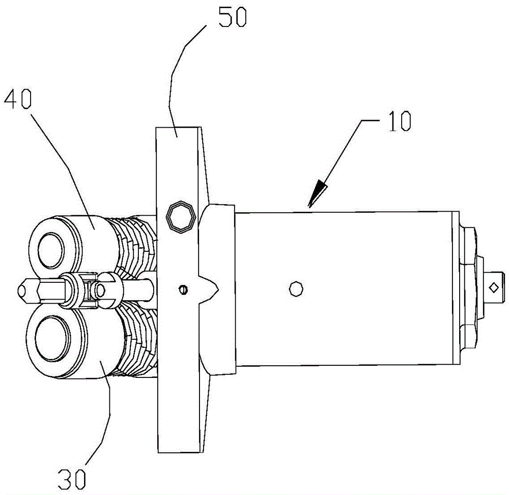
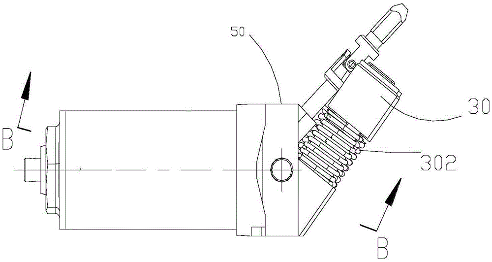
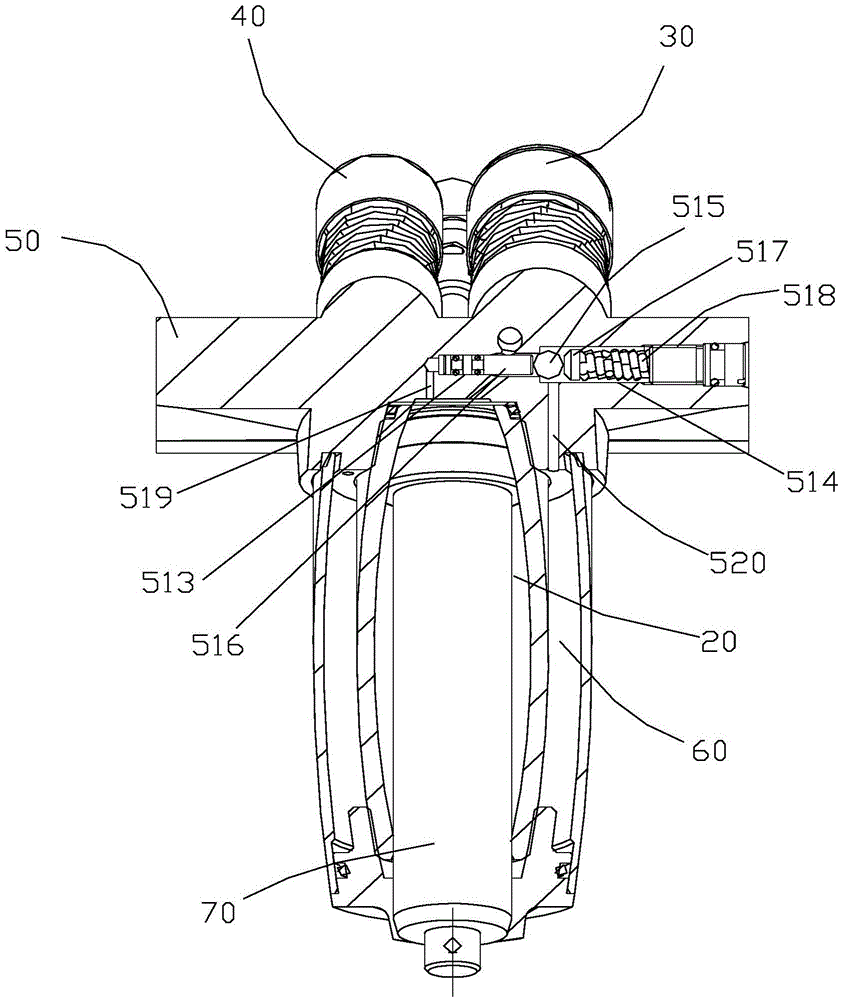
[0023] Such as Figure 1-3 As shown, a hydraulic jack for rapid lifting of a load includes a hydraulic oil pump 10, and the hydraulic oil pump 10 includes an oil cylinder 20, a large pump 30 that injects hydraulic oil into the oil cylinder 20, a small pump 40 that injects hydraulic oil into the oil cylinder 20, and an oil cylinder seat 50, the large pump 30 and the small pump 40 are fixedly connected to one side of the oil cylinder seat 50 respectively, and the oil cylinder 20 is fixedly connected to the other side of the oil cylinder seat 50, and the oil cylinder seat 50 is provided with a first channel 513 and a second Two channels 514, one end of the first channel 513 is connected with one end of the second channel 514, the diameter of the first channel 513 is smaller than the diameter of the second channel 514, and the connecting port between the fi...


PUM


Abstract

The invention relates to a hydraulic jack for rapidly lifting a load. The hydraulic jack comprises a hydraulic oil pump, wherein the hydraulic oil pump comprises an oil cylinder, a large pump, a small pump and an oil cylinder base; the larger pump is used for driving hydraulic oil into the oil cylinder; the small pump is used for driving hydraulic oil into the oil cylinder; the larger pump and the small pump are respectively fixedly connected with one side of the oil cylinder base; the oil cylinder is fixedly connected with the other side of the oil cylinder base; the oil cylinder base is provided with a first channel and a second channel; one end of the first channel is connected with one end of the second channel; the diameter of the first channel is smaller than that of the second channel; a connecting port of the first channel and the second channel is provided with a first steel ball for movably blocking the first channel and the second channel; the first channel is internally provided with a high-speed valve element for pushing the first steel ball to be separated from the connecting port of the first channel and the second channel; and the second channel is internally provided with an elastic element for providing an elastic stress for the first steel ball. When the load is smaller than a rated load, the double pumps simultaneously act, so that the jacking speed is high, the load is rapidly lifted, the work efficiency is high, the time consumption is low, and a great deal of time is saved.

Description

technical field [0001] The invention relates to a hydraulic jack for rapidly lifting a load Background technique [0002] A traditional hydraulic jack consists of a frame with front and rear wheels, on which a lifting arm, a long connecting rod, a tray, a bracket and a hydraulic oil pump for driving the lifting arm are installed, and the handle is connected to the hydraulic oil pump through a lifting handle , also includes a large pump and a small pump that inject hydraulic oil into the hydraulic oil pump, the inner cavity of the large pump and the inner cavity of the small pump are respectively connected with the hydraulic cylinder, and the large pump core and the small pump core are connected with the lift handle axially respectively. Connected, and the top end surfaces of the large and small pump cores are respectively in contact with the rollers mounted on the handle. [0003] When the jack is in the no-load lifting state, rotate the handle, and the roller presses on th...

Claims


Application Information

Patent Timeline
IPC IPC(8): B66F3/24B66F3/26B66F3/42
CPCB66F3/24B66F3/26B66F3/42
Inventor 史晓明殷子豪
Owner CHANGSHU TONGRUN AUTO ACCESSORY
Why Eureka
Try Eureka