
A method for anti-surge control system of converter gas compressor

A control system, converter gas technology, applied in the manufacture of converters, etc., can solve the problems of adjusting mutual interference, reducing operating efficiency, increasing equipment energy consumption, etc., to achieve the effect of stabilizing the pressure of the pipe network, improving operating efficiency, and reducing energy consumption

Active Publication Date: 2018-07-24
WISDRI ENG & RES INC LTD
View PDF6 Cites 0 Cited by
  • Summary
  • Abstract
  • Description
  • Claims
  • Application Information

AI Technical Summary

Problems solved by technology

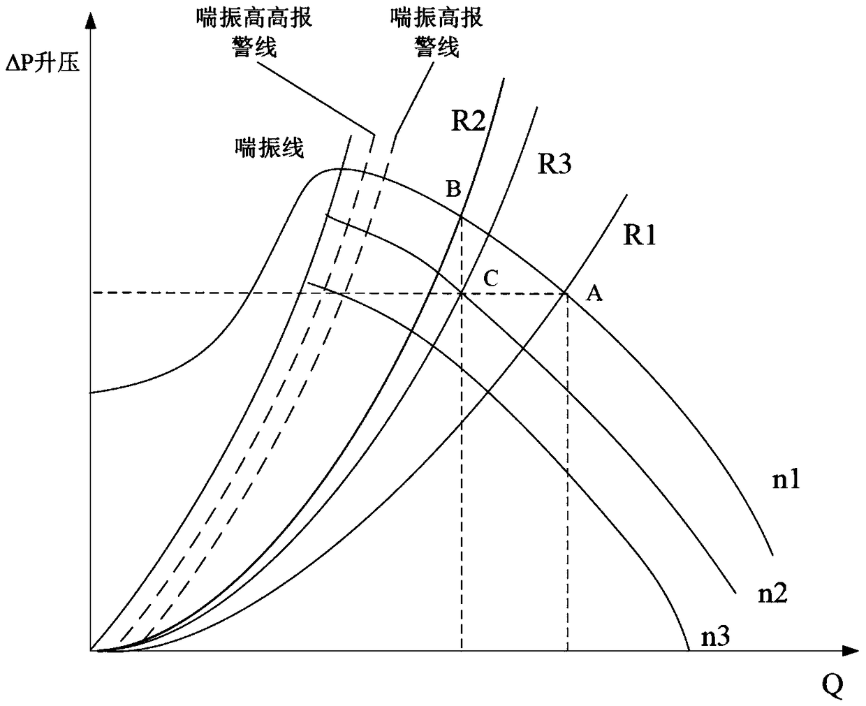
[0004] 1. In the specific design and production process of the gas pressurizer, in order to avoid surge, there is always a relatively large margin in its output capacity. The excess gas will flow back to the gas holder, thereby greatly increasing the energy consumption of the equipment. Reduced operating efficiency
[0005] 2. The adjustment of the outlet pressure of the pressurizer by the frequency conversion pressurizer and the return flow regulating valve interferes with each other, and there is a serious coupling relationship, which makes simultaneous adjustment impossible
[0006] 3. When the surge occurs, the return regulating valve cannot be opened quickly
After jumping out of the surge zone, overshoot is easy to occur, and manual adjustment is required based on manual experience

Method used


Image

  • A method for anti-surge control system of converter gas compressor
  • A method for anti-surge control system of converter gas compressor
  • A method for anti-surge control system of converter gas compressor

Examples


Embodiment Construction

[0025] The present invention will be described in further detail below in conjunction with specific embodiments and accompanying drawings. Embodiments of the present invention are described in detail below, examples of which are shown in the drawings, wherein the same or similar reference numerals designate the same or similar elements or elements having the same or similar functions throughout. The embodiments described below with reference to the accompanying drawings are exemplary, and are only used to explain the technical solution of the present invention, and should not be construed as limiting the present invention.

[0026] In the description of the present invention, the orientation or positional relationship indicated by the terms "inner", "outer", "longitudinal", "transverse", "upper", "lower", "top", "bottom" etc. are based on the drawings The orientations or positional relationships shown are only for the convenience of describing the invention and do not require ...


PUM


Abstract

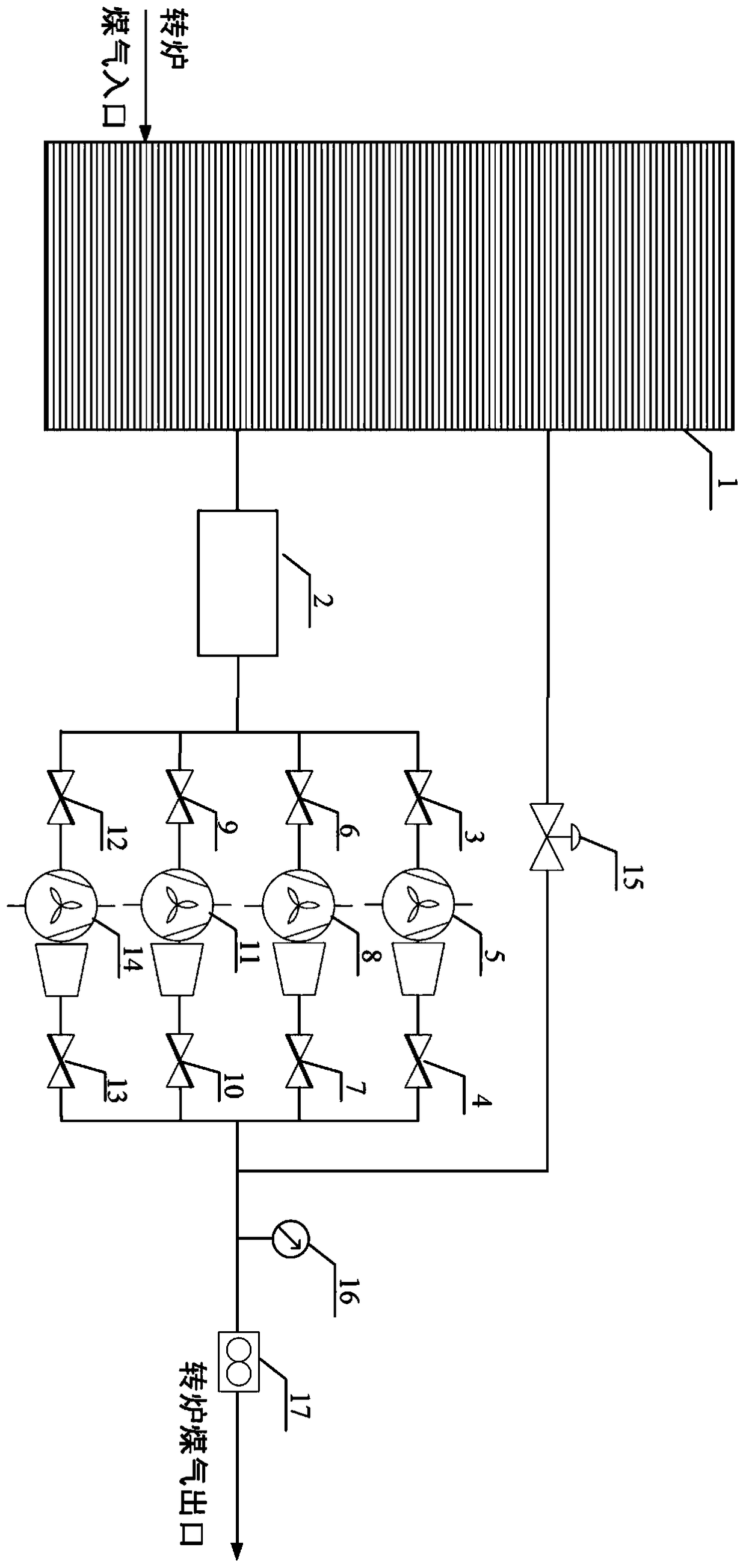
The invention provides an antisurge control system of a converter gas pressuring machine and a method. The antisurge control system of the converter gas pressuring machine comprises a converter gas cabinet body controlled by an electric control device, an electric dust collector, an inlet butterfly valve group, an outlet butterfly valve group, a backflow regulating valve, a pressure transmitter and a gas flowmeter, wherein the inlet butterfly valve group is communicated with the outlet butterfly valve group by a pressuring unit. The antisurge control system is characterized in that the converter gas cabinet body is provided with a converter gas inlet, a backflow inlet and a gas outlet; the pressuring unit comprises a gas inlet end and a gas outlet end; the gas inlet end is communicated with the inlet butterfly valve group through pipelines; the gas outlet end is communicated with the outlet butterfly valve group through the pipelines; the electric dust collector is communicated between the gas outlet and the inlet butterfly valve group through the pipelines; the pressure transmitter and the gas flowmeter are sequentially arranged at a pipeline communicating with an outlet of the outlet butterfly valve group; one end of the backflow regulating valve is communicated with a pipeline between the outlet butterfly valve group and the pressure transmitter through a pipeline; and the other end of the backflow regulating valve is communicated with the backflow inlet through a pipeline. By virtue of the structure above, antisurge control is realized, and good effects of improving the operating efficiency, reducing the energy consumption and stabilizing pipe network pressure are reached.

Description

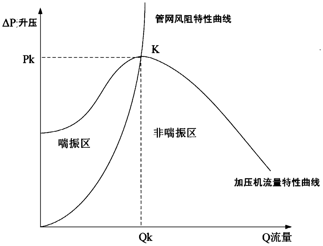
technical field [0001] The invention relates to the technical field of a converter gas cabinet system, in particular to providing a method for an anti-surge control system of a converter gas pressurizer. Background technique [0002] The recovery and reuse of converter gas is an important measure for enterprises to save energy, reduce consumption, and improve efficiency. It is also conducive to reducing pollution and improving the environment. The gas pressure in the converter gas cabinet is only about 3kPa, which cannot meet the pressure requirements of various production users of the enterprise, so the gas needs to be pressurized by a pressurizer. During the pressurization process, when the flow is small, the gas in the impeller and the diffuser channel will generate eddy currents. The formation and disappearance of the vortex will cause the flow channel of the liquid wheel to be blocked when it is formed, and cause frequent vibrations of the air flow and blades. , so tha...

Claims


Application Information

Patent Timeline
Patent Type & Authority Patents(China)
IPC IPC(8): C21C5/46
CPCC21C5/46
Inventor 李泽辉
Owner WISDRI ENG & RES INC LTD
Learn More