
Hollow glass with controllable dimming structure

A controllable, hollow technology, applied in parallel glass structures, optics, building components, etc., can solve problems such as unfavorable environmental protection, dazzling and strong light, and inability to change the direction of light irradiation, saving energy, low manufacturing costs, and solving problems. Sunshine effect

Active Publication Date: 2016-05-04
天津南玻节能玻璃有限公司
View PDF7 Cites 7 Cited by
  • Summary
  • Abstract
  • Description
  • Claims
  • Application Information

AI Technical Summary

Problems solved by technology

[0003] However, in the prior art, the dimming effect on insulating glass is realized by adding blinds or ordinary curtains to the insulating glass. However, the insulating glass added with blinds adjusts the light by adjusting the blinds, and the blinds or curtains can only play a role. The role of shading, but can not change the direction of the light, especially in summer, the light is often dazzling and strong, and if the light is completely covered by curtains, the room needs additional light sources, which is not conducive to environmental protection

Method used


Image

  • Hollow glass with controllable dimming structure
  • Hollow glass with controllable dimming structure
  • Hollow glass with controllable dimming structure

Examples


Embodiment 1

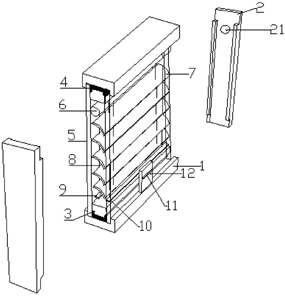
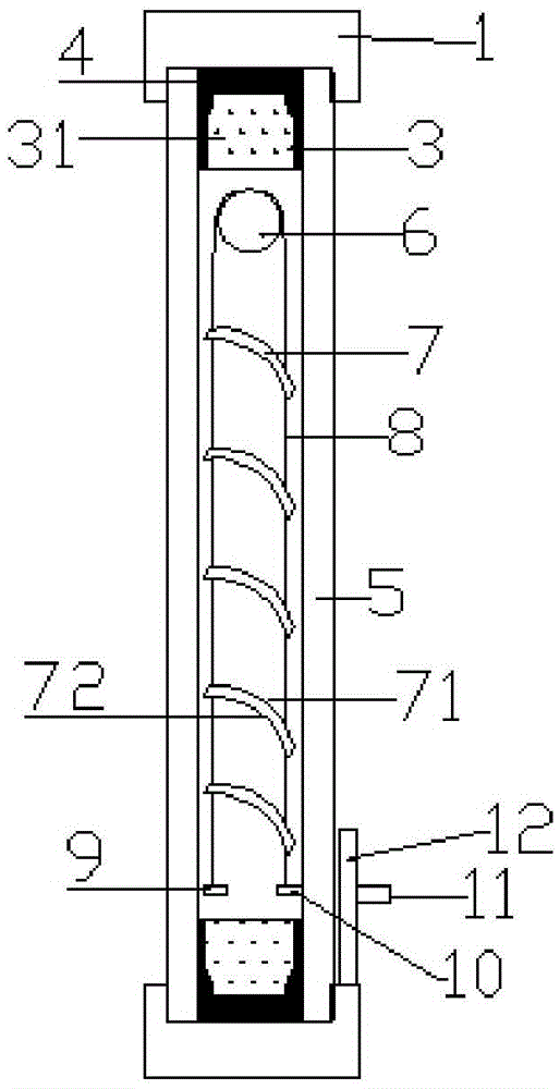
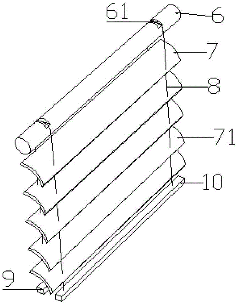
[0041] Such as figure 1As shown, a hollow glass with a controllable dimming structure includes a horizontal window frame 1, a vertical window frame 2 and a hollow glass sheet 5, and the hollow glass sheet 5 is selected from tempered glass, and the hollow glass sheet 5 is sandwiched between the horizontal window frame 1 and the longitudinal window frame 2, the hollow glass sheet 5 is provided with a spacer 3 and a sealant 4, and the hollow glass sheet 5 and the spacer 3 are sealed Glue 4 forms a hollow cavity, and the sealant 4 is a double-channel sealant comprising one sealant and two sealants, the first sealant is hot-melt butyl rubber, and the second sealant is silicone Structural glue, the hollow cavity is filled with air, the spacer 3 is a plastic warm edge strip, the spacer 3 is provided with a molecular sieve hollow glass desiccant, and the hollow cavity is provided with a controllable dimming structure, the controllable dimming structure includes a traction shaft 6 and...

Embodiment 2

[0044] Figure 7 Be another embodiment of the present invention, in the present embodiment, the basic structure of the present invention is the same as embodiment 1, the difference between embodiment 2 and embodiment 1 is that described spacer bar 3 selects stainless steel bar for use, so Molecular sieve hollow glass desiccant is provided in the stainless steel bar, argon gas is filled in the hollow cavity, coated glass is used for the hollow glass sheet 5, and the specular reflection surface 71 and the diffuse reflection surface 72 of the dimming panel 7 are are flat.


PUM


Abstract

The invention provides a hollow glass with a controllable dimming structure; the hollow glass comprises a transverse sash, a vertical sash, and a hollow glass sheet; the hollow glass sheet forms a hollow cavity; the controllable dimming structure is arranged in the hollow cavity, and comprises a traction shaft and a plurality of dimming plates; two turning traction wires wind the traction shaft and fix the dimming plates; the end portion of the turning traction wire is connected with a permanent magnet A, and the other end is connected with a balance block having equal weight with the permanent magnet A; a permanent magnet B attaching with the permanent magnet A is arranged outside the hollow glass sheet; the dimming plate comprises a mirror reflection surface and a diffuse reflection surface; the mirror reflection surface is a smooth surface; the diffuse reflection surface is a rugged surface; the mirror reflection surface faces to the outdoor direction; the diffuse reflection surface faces to the indoor direction; the traction shaft is fixedly connected with the vertical sash. The hollow glass can reflect the parallel light directly entering the room into non-parallel light, so the glaring light can become soft, and the dimming structure is adjustable in angle, thus saving energy.

Description

technical field [0001] The invention belongs to the field of hollow glass modification, and in particular relates to a hollow glass with a controllable dimming structure. Background technique [0002] Insulating glass is more and more widely used in the construction industry due to its good heat insulation, sound insulation, aesthetics and applicability, and can reduce the weight of buildings. With the development of insulating glass, people are no longer satisfied with the hollow structure of a single structure. Glass, the improvement of insulating glass, especially its dimming improvement, is increasing. [0003] However, in the prior art, the dimming effect on insulating glass is realized by adding blinds or ordinary curtains to the insulating glass. However, the insulating glass added with blinds adjusts the light by adjusting the blinds, and the blinds or curtains can only play a role. Especially in summer, the light is often dazzling and strong, and if the light is co...

Claims


Application Information

Patent Timeline
Patent Type & Authority Applications(China)
IPC IPC(8): E06B3/66E06B3/663E06B3/677G02B26/08
CPCE06B3/66E06B3/66361E06B3/677G02B26/08
Inventor 童帅
Owner 天津南玻节能玻璃有限公司
Learn More