
Eureka
For R&D, Eureka makes reading and utilizing patents & technical documents easy.
Eureka AIR
Designed for self-driven R&D workflows. Generate viable solutions, solve complex R&D challenges, empower your innovation with AI.

Eureka Materials
Designed for material experts only. Revolutionize your material R&D, from search, analyze, to developing new materials.

TechResearch
Generate reliable direction feasibility study reports for your R&D in just a few steps.

TechSeek
Discover and master advanced knowledge NOW. Basics, ideas, possibilities, all at once.

TechMind
As an expert in R&D Theories, TechMind can generates customized viable solutions instantly.

TechRisk
Analyze your overall solution with one click, know your potential R&D risks in advance.

TechMonitor
Get weekly tech updates, stay abreast of the latest tech innovations and key insights.
A spiral flow foam drilling machinery defoamer
A defoamer and helical flow technology, which is used in earth-moving drilling, flushing wellbore, wellbore/well components, etc., to achieve the effect of large foam processing capacity, high defoaming efficiency, and meeting defoaming requirements.
- Summary
- Abstract
- Description
- Claims
- Application Information
AI Technical Summary
Problems solved by technology
Method used
Image

Examples
Embodiment Construction
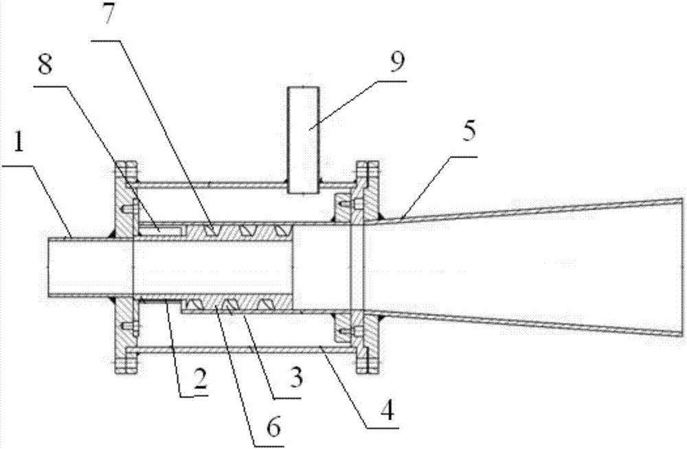
[0018] see figure 1 , figure 2 and image 3 Shown:
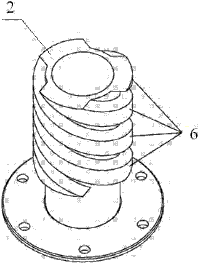
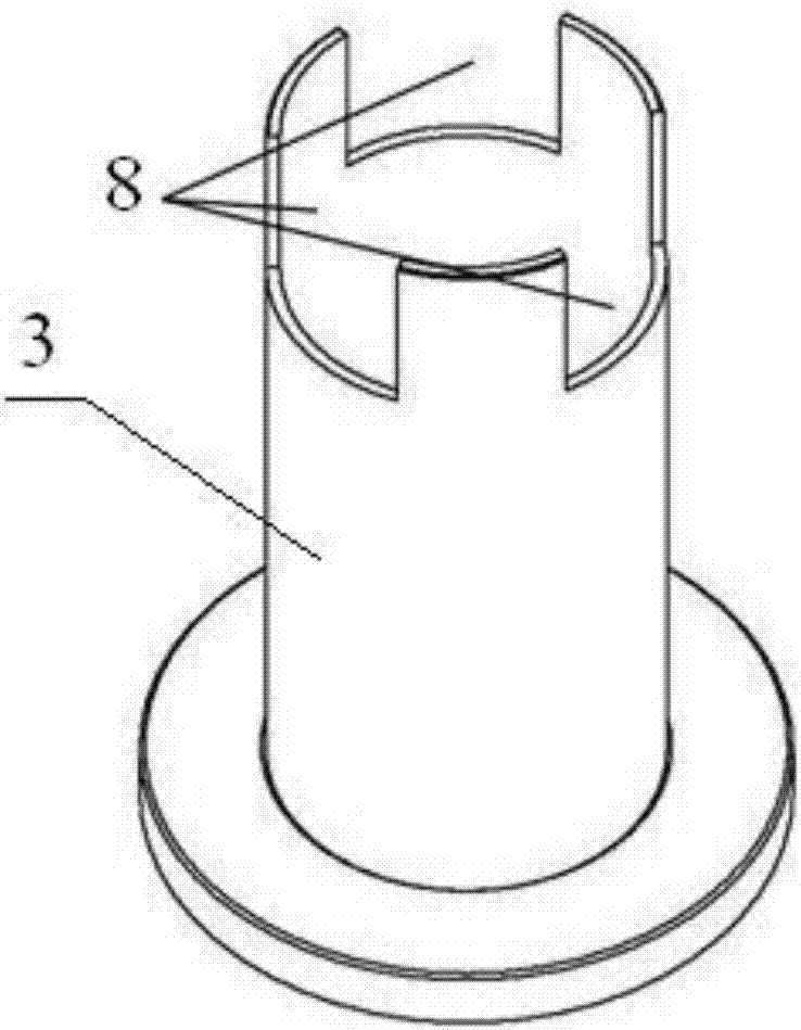
[0019] The spiral flow foam drilling machinery defoamer provided by the present invention includes a foam receiving pipe 1, a spiral pipe 2, a gas distribution pipe 3, an outer pipe 4 and a diffuser pipe 5, wherein one end of the foam receiving pipe 1 is connected to one end of the spiral pipe 2 Connection, the foam receiving pipe 1 is connected with the spiral pipe 2, the other end of the spiral pipe 2 is connected with the diffuser pipe 5, the air distribution pipe 3 is set on the spiral pipe 2, and the outer wall of the spiral pipe 2 is provided with several spiral protrusions 6, and the spiral protrusions The riser 6 closely cooperates with the inner wall of the air distribution pipe 3 to form several spiral passages 7, and the outer pipe 4 is sleeved on the air distribution pipe 3.
[0020] One end of the air distribution pipe 3 is provided with an air inlet 8 , and the outer pipe 4 is connected with an air inlet pi...
PUM
 Abstract
Description
Claims
Application Information
 - R&D Engineer
- R&D Manager
- IP Professional
- Industry Leading Data Capabilities
- Powerful AI technology
- Patent DNA Extraction
Browse by: Latest US Patents, China's latest patents, Technical Efficacy Thesaurus, Application Domain, Technology Topic, Popular Technical Reports.
© 2024 PatSnap. All rights reserved.Legal|Privacy policy|Modern Slavery Act Transparency Statement|Sitemap|About US| Contact US: help@patsnap.com