Convolution cavitation device

A cavitator and eddy current technology, which is applied in the device field of equipment, can solve problems such as complex operation process, and achieve the effect of simple equipment structure, large processing capacity and low manufacturing cost

Inactive Publication Date: 2005-04-13
SHANGHAI JIAO TONG UNIV
View PDF1 Cites 38 Cited by
  • Summary
  • Abstract
  • Description
  • Claims
  • Application Information

AI Technical Summary

Problems solved by technology

Due to the need to periodically heat the saturated filter material to remove the adsorbed grease d

Method used


Image

  • Convolution cavitation device
  • Convolution cavitation device
  • Convolution cavitation device

Examples


Embodiment Construction

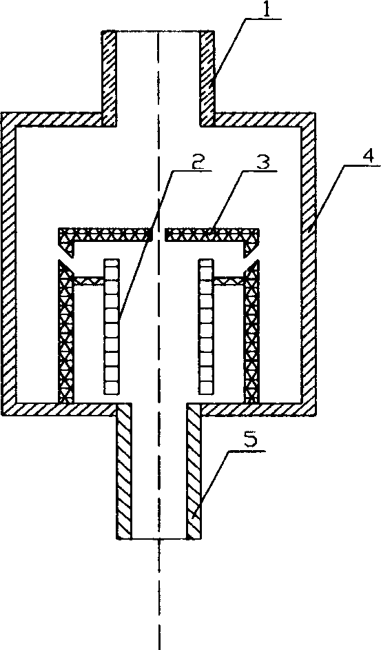
[0015] Such as figure 1 As shown, the present invention comprises: liquid inlet pipe 1, three coaxial inner cylinders 2, middle cylinder 3, outer cylinder 4 and outlet section 5, wherein outer cylinder 4 and middle cylinder 3 have their respective The top and the common bottom, while the inner cylinder 2 is a hollow cylinder, each has its own entrance at the center of the top of the middle cylinder 3 and the outer cylinder 4, and the middle cylinder 3 and the outer cylinder 4 have a common bottom, Their bottoms are connected with the inlet end of the nozzle 5, and the inner cylinder 2 is connected with the middle cylinder 3 with four beams evenly distributed in the radial direction. A plurality of tangential slits are arranged on the wall of the upper half of the middle cylinder 3 . When water-containing emulsified oil or emulsified oily waste water enters the outer cylinder 4 of the vortex cavitator at a certain pressure and flow rate through the pump, part of the fluid flow...


PUM


Abstract

The eddy cavitating unit used in the technological field of chemical separation consists of liquid inlet pipe and three coaxial cylinders including inner cylinder, middle cylinder and outer cylinder, the outer cylinder and the middle cylinder have individual tops with central inlet and common bottom, and the inner cylinder is a hollow cylinder and is connected to the middle cylinder via four radial cross beams. Or, the eddy cavitating unit consists of liquid inlet pipe, paraboloidal cone, disc with slit, flow guide plate and nozzle. Or, the eddy cavitating unit consists of liquid inlet pipe, outer paraboloidal cone, inner funnel cone and nozzle.

Description

technical field [0001] The invention relates to a device in oil-water separation equipment, in particular to a vortex cavitator, which is used in the technical field of chemical separation. Background technique [0002] Most of the crude oil produced from oil wells is mixed with natural gas and brine, and the "crude oil" obtained after the natural gas and free water are separated by an oil-gas separator is generally still a water-in-oil containing a certain amount of salt and water (W / O) type emulsion. The presence of salt and water in crude oil will increase the load on pumps, pipelines and storage tanks, and will cause corrosion and scaling of equipment and pipelines, as well as catalyst poisoning. Therefore, crude oil must be desalted and dehydrated before transportation and processing to make it The salinity and water content of the salt meet certain requirements. The oil extraction, oil refining, oil storage and transportation of the petroleum industry, petrochemical...

Claims


Application Information

Patent Timeline
IPC IPC(8): B01D17/04
Inventor 贾金平徐金球侯士兵王亚林
Owner SHANGHAI JIAO TONG UNIV
Why Eureka
Try Eureka