A device and system for storing and releasing mechanical energy

A mechanical energy and energy storage technology, which is applied in the direction of mechanical power generating mechanisms, mechanical equipment, machines/engines, etc., can solve the problems of mains power supply, high current consumption of electromagnets, and high cost of controllers. The effects of electrical wiring construction, low power consumption, and high torque bearing capacity

Active Publication Date: 2018-05-04
SHENZHEN YIAIKESI INFORMATION TECH CO LTD
View PDF6 Cites 0 Cited by
  • Summary
  • Abstract
  • Description
  • Claims
  • Application Information

AI Technical Summary

Problems solved by technology

Although manual operation is stable and reliable, it has low efficiency and high labor costs; the electromagnet consumes a large amount of current, and the release of the same mechanical energy requires a large drive current and a maintenance current; the cost of the stepper motor-driven controller is relatively high, and the subsequent Both cannot get rid of the constraints of mains power supply

Method used


Image

  • A device and system for storing and releasing mechanical energy
  • A device and system for storing and releasing mechanical energy
  • A device and system for storing and releasing mechanical energy

Examples


Embodiment 1

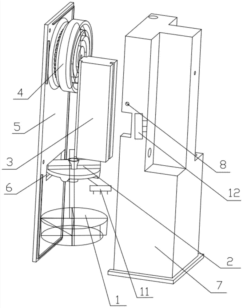
[0027] like figure 1 As shown, this example provides a device for storing and releasing mechanical energy, including: a reduction motor 1, a positioning cam 2, a stop bar 3 and a main pulley 4, the main pulley 4 is movably connected with the stop bar 3, and the The positioning cam 2 realizes the positioning control of the main pulley 4 through the stop rod 3, and the positioning cam 2 is connected with the stop rod 3 and the reduction motor 1 respectively; wherein, the main pulley 4 moves along the first Mechanical energy storage is realized when rotating in one direction, and the energy storage is completed when the main pulley 4 stops rotating. At this time, the positioning cam 2 locks the main pulley 4 through the stop lever 3, and the gear motor 1 receives the trigger After the instruction, the positioning cam 2 realizes the unlocking of the main pulley 4 through the stop lever 3, and the main pulley 4 rotates along the second direction to release mechanical energy, and th...

Embodiment 2

[0037] This example also provides a system for storing and releasing mechanical energy, including the device for storing and releasing mechanical energy as described in Example 1.

[0038] The mechanical energy storage and release system described in this example is preferably applied to the automatic window closing system of a smart home. The mechanical energy storage and release device described in Embodiment 1 can be fixedly installed by the window; when the window is opened, it will be pulled out The steel wire described in Embodiment 1 locks the main pulley 4; the device for storing and releasing the mechanical energy is powered by a battery and receives the control signal from the smart home control center with low power consumption; when the user goes out, he forgets to close the window or the controller When severe weather such as thunderstorms, strong winds, and excessive PM2.5 is detected, the windows can be remotely or intelligently triggered to close.

[0039] The ...


PUM


Abstract

The invention provides a mechanical energy storing and releasing device and a system thereof. The device comprises a gear motor, a positioning cam, a stop rod and a main pulley, wherein the main pulley is movably connected with the stop rod; the positioning cam controls positioning of the main pulley through the stop rod; and the positioning cam is respectively connected with the stop rod and the gear motor. When the main pulley rotates in the first direction, mechanical energy storage is implemented, energy storage is finished when the main pulley stops rotating, at the moment, the positioning cam locks the main pulley through the stop rod, after the gear motor receives a triggering command, the positioning cam unlocks the main pulley through the stop rod, the main pulley rotates in the second direction to release the mechanical energy, and the first rotating direction is opposite to the second rotating direction. Through the ingenious mechanical design, long enough stroke can be realized under the condition of small size, and requirements on miniaturization and industrial appearance design of products are met.

Description

technical field [0001] The present invention relates to an energy storage and release device, in particular to a mechanical energy storage and release device, and to a system including the mechanical energy storage and release device. Background technique [0002] Most of the existing mechanical energy release systems rely on manual operation, or are driven by electromagnets or stepping motors. Although manual operation is stable and reliable, it has low efficiency and high labor costs; the electromagnet consumes a large amount of current, and the release of the same mechanical energy requires a large drive current and a maintenance current; the cost of the stepper motor-driven controller is relatively high, and the subsequent Both cannot get rid of the constraints of mains power supply. Contents of the invention [0003] The technical problem to be solved by the present invention is to provide a mechanical energy storage and release device with low power consumption, low...

Claims


Application Information

Patent Timeline
Patent Type & Authority Patents(China)
IPC IPC(8): F03G7/00
CPCF03G7/00
Inventor 薛振峰
Owner SHENZHEN YIAIKESI INFORMATION TECH CO LTD
Why Eureka
Try Eureka