
Heat pump system

A heat pump system and outdoor heat exchanger technology, applied in the field of air conditioning, can solve the problems of compressor oil shortage and inability to achieve continuous oil return, and achieve the effect of ensuring stable operation and ensuring oil return speed.

Pending Publication Date: 2016-05-04
GREE ELECTRIC APPLIANCES INC
View PDF5 Cites 5 Cited by
  • Summary
  • Abstract
  • Description
  • Claims
  • Application Information

AI Technical Summary

Problems solved by technology

[0005] The embodiment of the present invention provides a heat pump system to solve the problem in the prior art that the heat pump system cannot achieve continuous oil return when the three-cylinder operation is high-capacity output, resulting in a lack of oil for the compressor

Method used


Image

  • Heat pump system
  • Heat pump system

Examples


Embodiment Construction

[0021] The present invention will be described in further detail below in conjunction with the accompanying drawings and specific embodiments, but not as a limitation of the present invention.

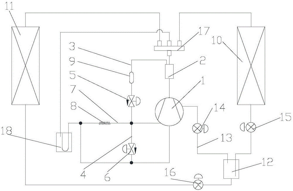
[0022] Please refer to figure 2 As shown, the present invention provides a heat pump system, including a compressor 1 and an oil separator 2. The heat pump system also includes a first oil return pipeline 3 and a second oil return pipeline 4. The first oil return pipeline 3 is connected to the oil separator Between the outlet of the device 2 and the switching port of the number of cylinders of the compressor 1, the first oil return line 3 is provided with a first control valve 5, and the second oil return line 4 is connected to the switching port of the number of cylinders of the compressor 1 and the compressor Between the suction port of compressor 1, the second oil return line 4 is provided with a second control valve 6, the outlet of the first control valve 5 is connected with the ...


PUM


Abstract

The invention discloses a heat pump system. The heat pump system comprises a compressor and an oil separator and further comprises a first oil returning pipeline and a second oil returning pipeline; the first oil returning pipeline is connected between the oil separator and a cylinder number switching opening of the compressor, and a first control valve is arranged on the first oil returning pipeline; the second oil returning pipeline is connected between the cylinder number switching opening of the compressor and an air suction opening of the compressor, and a second control valve is arranged on the second oil returning pipeline; and a third oil returning pipeline is connected between an outlet of the first control valve and the air suction opening of the compressor, and a pressure control unit for controlling pressure at the outlet of the first control valve is arranged on the third oil returning pipeline. According to the heat pump system, the problem that in the prior art, a heat pump system cannot carry out continuous oil returning during three-cylinder running high capacity output, and consequently, oil starvation appears in the compressor is solved.

Description

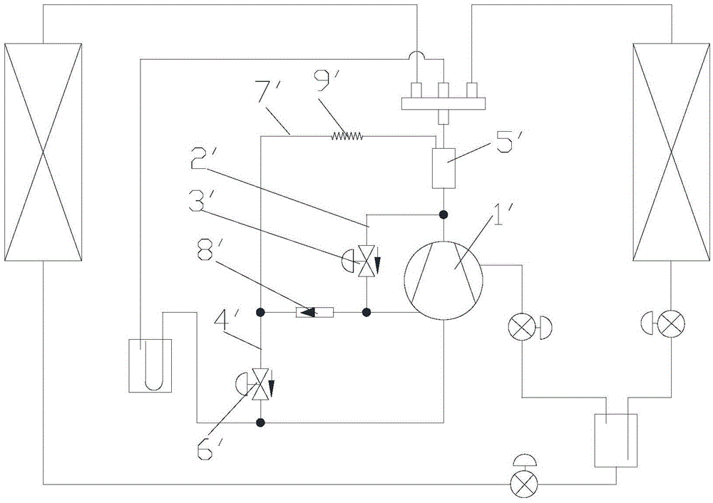
technical field [0001] The present invention relates to the technical field of air conditioning, in particular to a heat pump system. Background technique [0002] Such as figure 1 As shown, a heat pump system is provided in the prior art. A first oil return line 2' is provided between the high-pressure exhaust port of the compressor 1' and the cylinder number switching port of the heat pump system. The first oil return line 2 A first solenoid valve 3' is set on the ', a second oil return pipeline 4' is set between the cylinder number switching port of the compressor 1' and the low-pressure suction port of the compressor 1', and a second oil return line 4' is set between the oil separator 5' and the A third oil return line 7' is set between the second solenoid valve 6' on the second oil return line 4', and it is set on the line between the cylinder number switching port of the compressor 1' and the second solenoid valve 6' There is a one-way valve 8', and an oil return cap...

Claims


Application Information

Patent Timeline
Patent Type & Authority Applications(China)
IPC IPC(8): F25B1/00F25B31/00F25B41/04F25B41/20
CPCF25B1/00F25B31/004F25B41/20
Inventor 黄玉优吴永和
Owner GREE ELECTRIC APPLIANCES INC
Learn More