Discriminating method for particles in interference particle imaging system sampling area

A technology of particle imaging and sampling area, applied in the field of optical measurement, can solve problems that have not been raised

Inactive Publication Date: 2016-05-04
TIANJIN UNIV
View PDF7 Cites 11 Cited by
  • Summary
  • Abstract
  • Description
  • Claims
  • Application Information

AI Technical Summary

Problems solved by technology

Therefore, the method of judging whether the particle is in the sampling area of ​​the IPI system is very important.

Method used


Image

  • Discriminating method for particles in interference particle imaging system sampling area
  • Discriminating method for particles in interference particle imaging system sampling area
  • Discriminating method for particles in interference particle imaging system sampling area

Examples


Embodiment 1

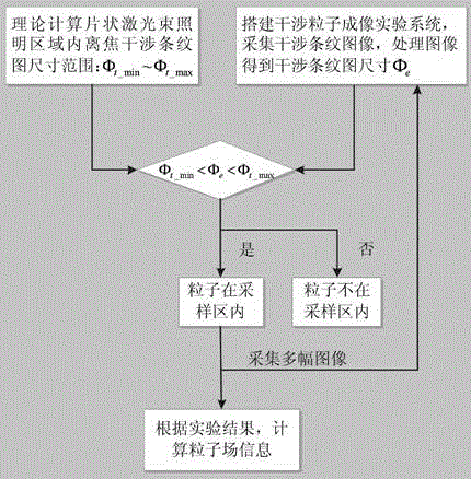
[0023] Such as figure 1 The flow chart of the particle discrimination method in the sampling area of ​​the interference particle imaging system of the present invention is shown.

[0024] First, theoretically deduce the size range of the interference fringe pattern in the area illuminated by the sheet laser beam Φ t_min ~Φ t_max , the formula for calculating the size of the interference fringe pattern is as follows

[0025] Φ t = 2 g t a n ( w / 2 ) β · Δ x - - - ( 1 )

[0026] Among them, g represents the focal length, w represents the system collection angl...


PUM


Abstract

The invention discloses a discriminating method which is used for particles in an interference particle imaging system sampling area and applied to an interference particle imaging system, and belongs to the technical field of optical measurement. The method comprises the steps that the size range phit_min-phit_max of an interference fringe pattern in a flaky laser beam illumination area is derived according to an interference fringe pattern size calculation formula; an interference particle imaging experiment system is built, an interference particle fringe image is collected at the position, g away from the focal length, of the system, the actual interference fringe pattern size phie is obtained by processing the image, whether the particles are in the sampling area or not is judged, if phit_min<phi e<phit_max, the particles are in the sampling area, and otherwise, the particles are not in the sampling area; multiple images are collected, whether all the particles are in the sampling area or not is judged, experimental results are recorded, and experimental data is counted; particle field information such as the particle number density is calculated according to the experimental results. For judging whether the particles are in the interference particle imaging system sampling area, the novel method is supplied, and a strong basis is supplied to measurement of the particle concentration and the particle number density.

Description

technical field [0001] The invention relates to a method for judging whether a particle is in a sampling area of ​​a defocused imaging system, especially applied to an interference particle imaging system, and belongs to the technical field of optical measurement. Background technique [0002] Interferometric Particle Imaging (IPI) technology is widely used in particle field measurement. Its basic principle is that spherical particles are irradiated by sheet laser beams, the particles are scattered, and interference fringe patterns are formed on the particle defocused image plane. By measuring the center position of the interference fringe pattern The position information of the particles can be obtained, and the particle size information can be obtained by calculating the interference fringe frequency. The IPI system is an out-of-focus imaging system, and the image plane is located at the out-of-focus position, that is, no point on the object plane can form a clear image on...

Claims


Application Information

Patent Timeline
IPC IPC(8): G01N15/06G01N15/02
CPCG01N15/06G01N15/0227
Inventor 张红霞刘京贾大功刘铁根张以谟
Owner TIANJIN UNIV
Why Eureka
Try Eureka