Particle imaging system with a varying flow rate

a flow rate and imaging system technology, applied in particle and sedimentation analysis, measurement devices, instruments, etc., can solve the problems of limiting exposure, time-consuming scanning of a large number of entities, and limited exposure time of a single frame, so as to increase exposure times and achieve high image capture rate

Active Publication Date: 2007-12-11
PROTEINSIMPLE
View PDF12 Cites 14 Cited by
  • Summary
  • Abstract
  • Description
  • Claims
  • Application Information

AI Technical Summary

Benefits of technology

[0017]The invention provides a system and method for analyzing particles in a fluid wherein the fluid within the sample cell is periodically stopped, or slowed down, for image capturing and moved rapidly between image capturing events. Advantageously, the present invention allows to increase exposure times to form quality images at a low illumination intensity, which is particularly significant for fluorescent imaging, while acquiring images at a high image capture rate.

Problems solved by technology

If this process is carried out manually, scanning a large number of entities is time consuming.
For particle imaging systems employing a constant fluid flow, exposure time of a single frame is limited by the effect of streaking when particles within the fluid change their positions significantly during exposure.
High throughput of an imaging system is associated with a high velocity of the fluid, which causes streaking, undesirable and limiting the exposure.
The shorter exposure time requires more intense illumination, which, in turn, can adversely affect the sample, especially in applications related to microbiology and medicine.

Method used


Image

  • Particle imaging system with a varying flow rate
  • Particle imaging system with a varying flow rate
  • Particle imaging system with a varying flow rate

Examples


Embodiment Construction

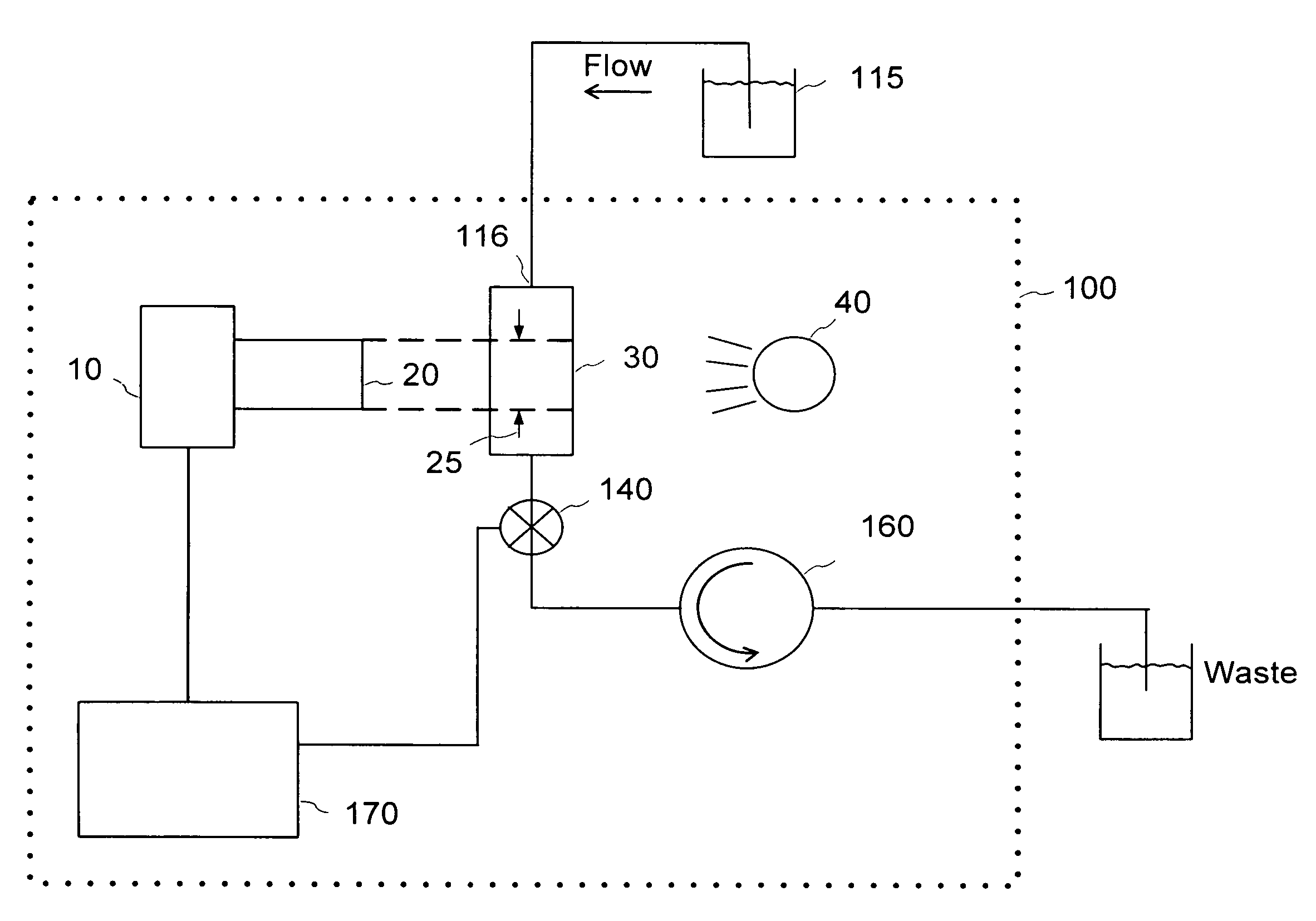
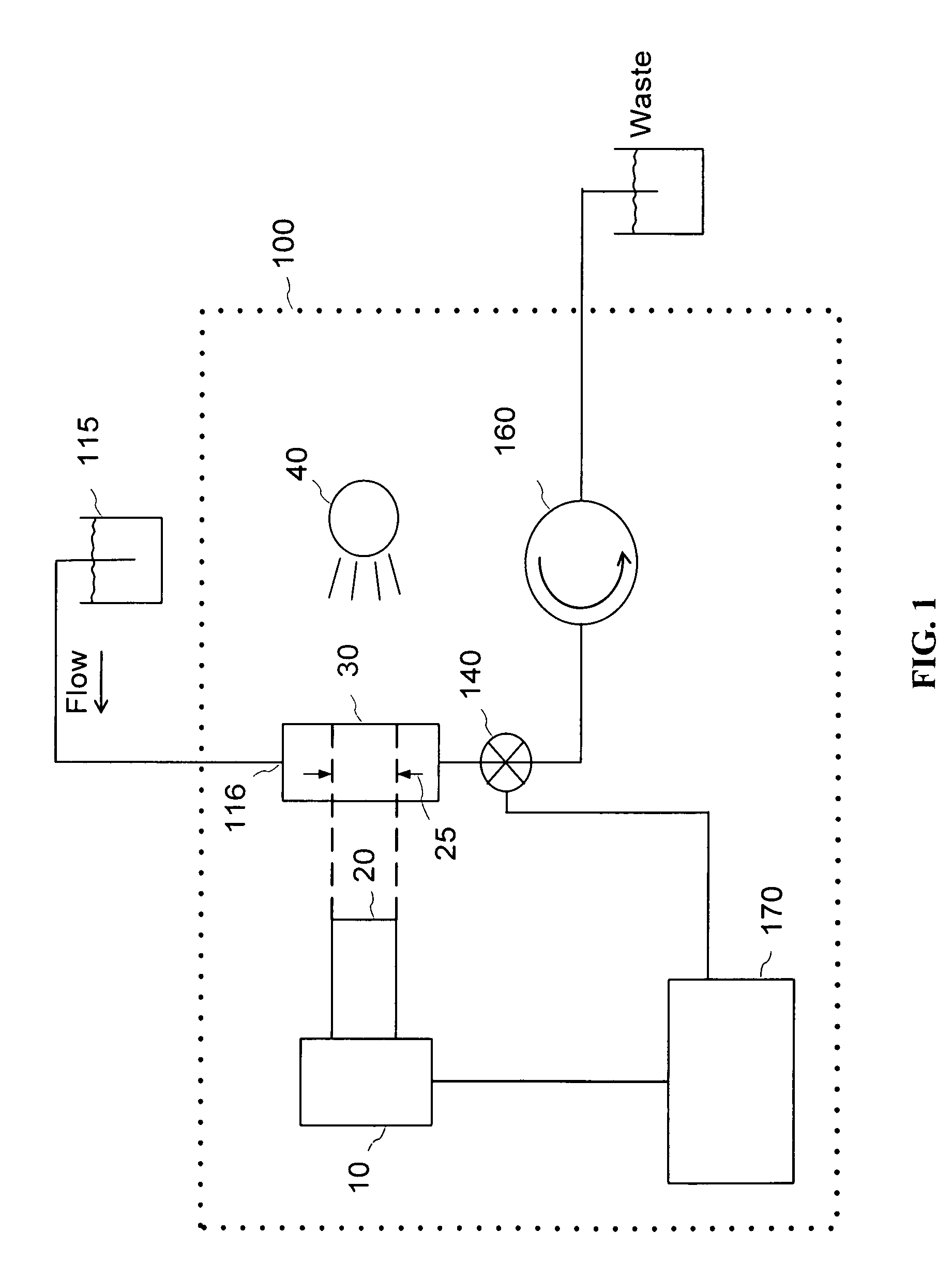
[0024]Exemplary embodiments of the present invention will now be described with reference to FIG. 1. A particle imaging system 100 has a sample cell 30 for containing samples of fluid flowing therethrough, and a conduit 116 for providing samples of the fluid containing suspended particles to be tested into the sample cell 30. The system 100 further includes a flow control means for controllably varying the fluid flow through the sample cell, an imaging means for capturing a plurality of images of the particles within the sample cell, and a processor 170, hereinafter also referred to as a computer 170, for processing the plurality of images to obtain data related to the particles.

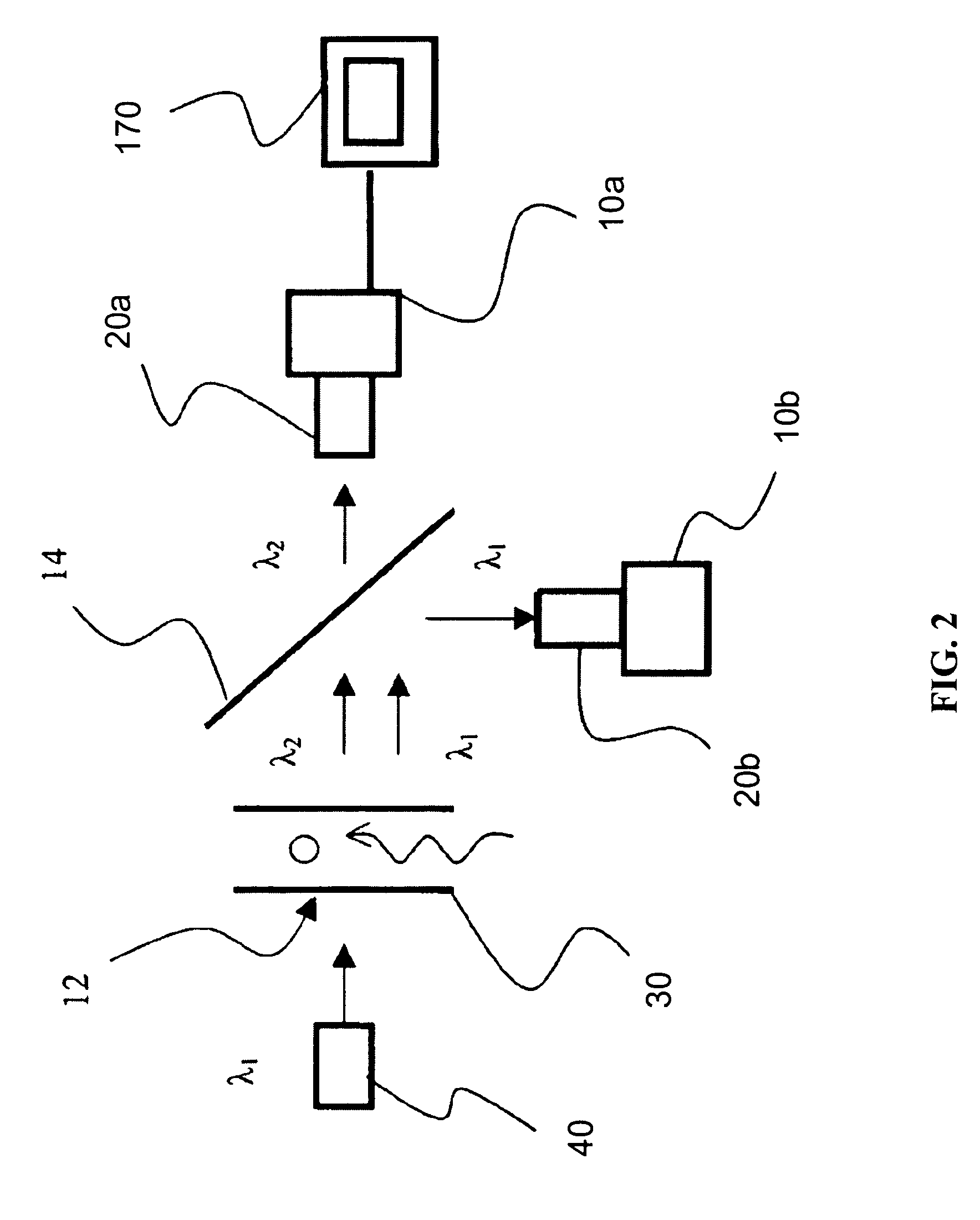
[0025]In one embodiment wherein the imaging means include a light source 40 disposed outside of the sample cell 30 for illuminating the particles therein, the sample cell 30, also referred to as a flow cell 30 or simply as the cell 30, is substantially transparent for light of the light source 40, or has at ...


PUM

PropertyMeasurementUnit
Reynolds numberaaaaaaaaaa
depthaaaaaaaaaa
depthaaaaaaaaaa

Abstract

A particle imaging system and a method provided for analyzing particles in a fluid; the system comprising a means for capturing image data of the fluid within a sample cell, and a means for flow control, a valve and a pump, wherein the fluid within the sample cell is periodically stopped, or slowed down, for image capturing and moved rapidly between image capturing events. Advantageously, the present invention allows to increase exposure times, which is particularly significant for fluorescent imaging at low illumination levels.

Description

CROSS-REFERENCE TO RELATED APPLICATIONS[0001]The present invention claims priority from U.S. Provisional Patent Application No. 60 / 670,670 filed Apr. 13, 2005, entitled “Particle Imaging System Having a Periodically Varying Flow Rate”, which is incorporated herein by reference.FIELD OF THE INVENTION[0002]The present invention relates to measuring a characteristic of a particle or plurality of particles within a sample of a fluid by optical imaging, wherein the fluid flows through a sample cell at a varying rate.BACKGROUND OF THE INVENTION[0003]Instruments which analyze small particles suspended in liquids in order to provide parameter distribution data or classification of the particle types are of practical importance in fields which include microbiology, medicine, and drinking / wastewater processing. Some of these instruments form images of a volume of liquid along with any particles contained within this volume and analyze these images to obtain the required parameters. In order t...

Claims


Application Information

Patent Timeline
Patent Type & Authority Patents(United States)
IPC IPC(8): G01N15/02
CPCG01N15/1404G01N15/1463G01N15/1459G01N2015/1409
Inventor KING, FREDERICK DAVID
Owner PROTEINSIMPLE
Why Eureka
Try Eureka