Guided charged particle imaging/treatment apparatus and method of use thereof

a technology of charged particle and imaging apparatus, which is applied in the field of imaging and treating tumors, can solve the problems of reducing the ability to repair damaged dna, affecting the detection accuracy of tumors,

Inactive Publication Date: 2017-01-19
LEE W DAVIS +2
View PDF1 Cites 13 Cited by
  • Summary
  • Abstract
  • Description
  • Claims
  • Application Information

AI Technical Summary

Problems solved by technology

These particles damage the DNA of cells, ultimately causing their death.
Cancerous cells, because of their high rate of division and their reduced ability to repair damaged DNA, are particularly vulnerable to attack on their DNA.

Method used


Image

  • Guided charged particle imaging/treatment apparatus and method of use thereof
  • Guided charged particle imaging/treatment apparatus and method of use thereof
  • Guided charged particle imaging/treatment apparatus and method of use thereof

Examples


example v

[0082]Still referring to FIG. 2C and FIG. 2D, a fifth example of using the triode extraction system 210 with varying types of ion sources is provided. The triode extraction system 210 is optionally used with an electron cyclotron resonance (ECR) ion source, a dual plasmatron ion source, an indirectly heated cathode ion source, a Freeman type ion source, or a Bernas type ion source.

Example VI

[0083]Herein, for clarity of presentation and without loss of generality, the triode extraction system 210 is integrated with an electron cyclotron resonance source. Generally, the electron resonance source generates an ionized plasma by heating or superimposing a static magnetic field and a high-frequency electromagnetic field at an electron cyclotron resonance frequency, which functions to form a localized plasma, where the heating power is optionally varied to yield differing initial energy levels of the ions. As the electron resonance source: (1) moves ions in an arc in a given direction and ...

example vii

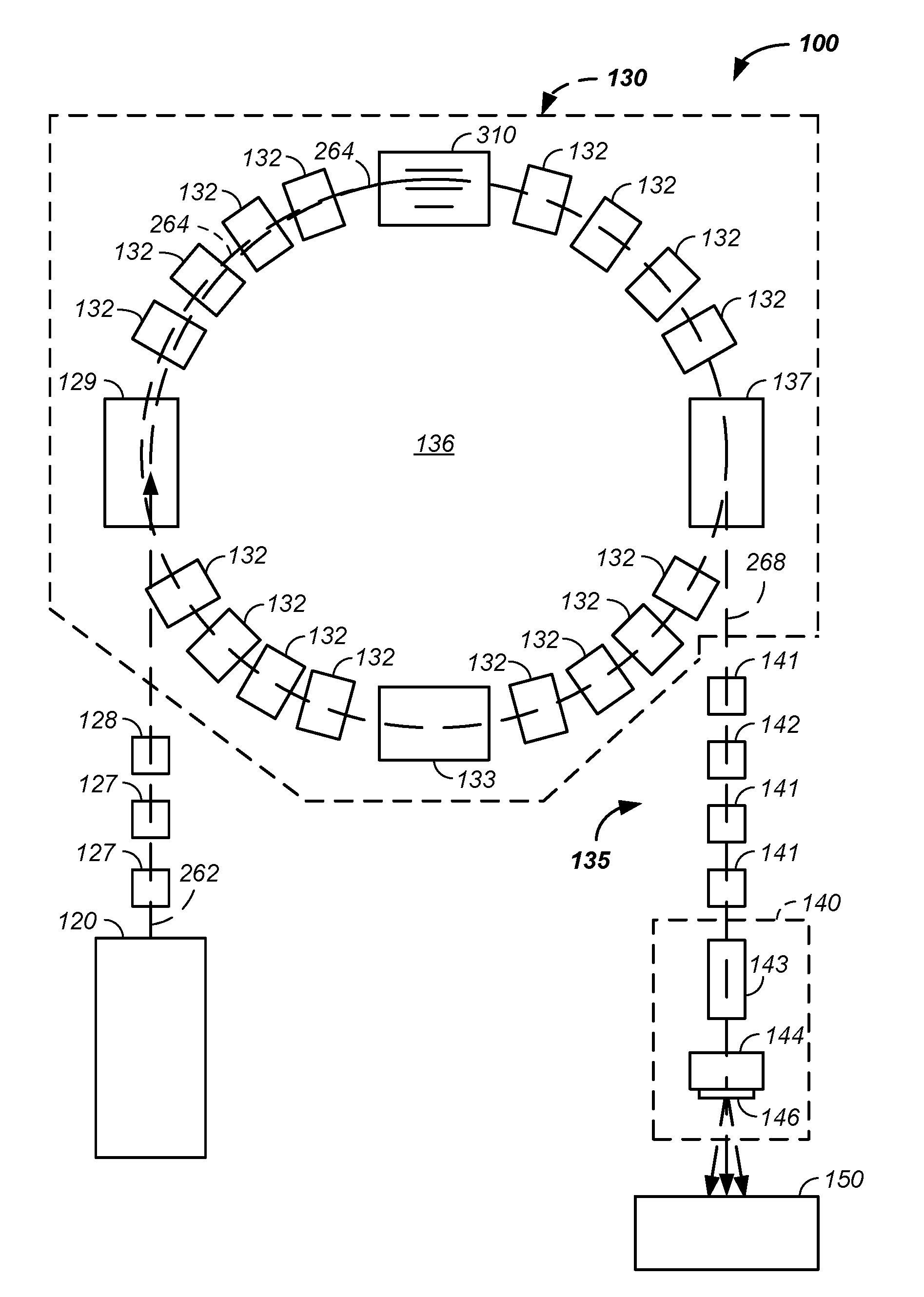
[0085]Still referring to FIG. 2C and FIG. 2D, optionally and preferably geometries of the gating electrode 204 and / or the extraction electrode 206 are used to focus the extracted ions along the initial ion beam path 262.

example viii

[0086]Still referring to FIG. 2C and FIG. 2D, the lower emittance of the electron cyclotron resonance triode extraction system is optionally and preferably coupled with a downbeam or downstream radio-frequency quadrupole, used to focus the beam, and / or a synchrotron, used to accelerate the beam.


PUM


Abstract

The invention comprises a method and apparatus for tracking and / or imaging impact of a particle beam treating a tumor using one or more imaging systems positionable about the tumor, such as a positron emission tracking and / or imaging system, where resulting tracking / imaging data: dynamically determines a treatment beam position, tracks a history of treatment beam positions, guides the treatment beam, and / or images a tumor before, during, and / or after treatment with the charged particle beam.

Description

CROSS-REFERENCES TO RELATED APPLICATIONS[0001]This application is a continuation-in-part of U.S. patent application Ser. No. 15 / 167,617 filed May 27, 2016, which is:[0002]a continuation-in-part of U.S. patent application Ser. No. 15 / 152,479 filed May 11, 2016, which:[0003]is a continuation-in-part of U.S. patent application Ser. No. 14 / 216,788 filed Mar. 17, 2014,[0004]which is a continuation-in-part of U.S. patent application Ser. No. 13 / 087,096 filed Apr. 14, 2011, which claims benefit of U.S. provisional patent application No. 61 / 324,776 filed Apr. 16, 2010; and[0005]is a continuation-in-part of U.S. patent application Ser. No. 13 / 788,890 filed Mar. 7, 2013;[0006]is a continuation-in-part of U.S. patent application Ser. No. 14 / 952,817 filed Nov. 25, 2015, which is a continuation-in-part of U.S. patent application Ser. No. 14 / 293,861 filed Jun. 2, 2014, which is a continuation-in-part of U.S. patent application Ser. No. 12 / 985,039 filed Jan. 5, 2011, which claims the benefit of U....

Claims


Application Information

Patent Timeline
Patent Type & Authority Applications(United States)
IPC IPC(8): A61N5/10
CPCA61N5/1065A61N2005/1087A61N5/1077A61N5/1039A61N5/1082A61B6/032A61B6/4258A61B6/5205A61N5/1067A61N5/1069A61N5/107G21K1/08G21K5/04A61N5/1037A61N2005/1054A61N2005/1095A61N2005/1097A61B6/4216A61B6/4266A61B6/467A61B6/4092A61N5/1049A61N2005/1052A61N5/1044
Inventor LEE, W. DAVISAMATO, MARK R.MICHAUD, SUSAN L.
Owner LEE W DAVIS
Why Eureka
Try Eureka