Well treatment with dissolvable polymer

a dissolvable polymer and well technology, applied in the direction of well accessories, separation processes, insulation, etc., can solve the problems of fluid loss, equipment, fluid leakage into porous rock at an undesirable rate, and reducing the efficiency of fluid placement with respect to time, etc., to achieve the effect of restoring permeability to the formation surfa

Inactive Publication Date: 2008-07-15
SCHLUMBERGER TECH CORP
View PDF49 Cites 80 Cited by
  • Summary
  • Abstract
  • Description
  • Claims
  • Application Information

AI Technical Summary

Benefits of technology

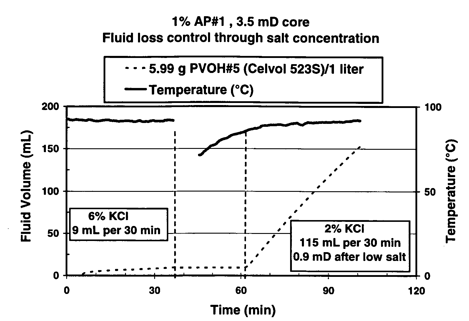
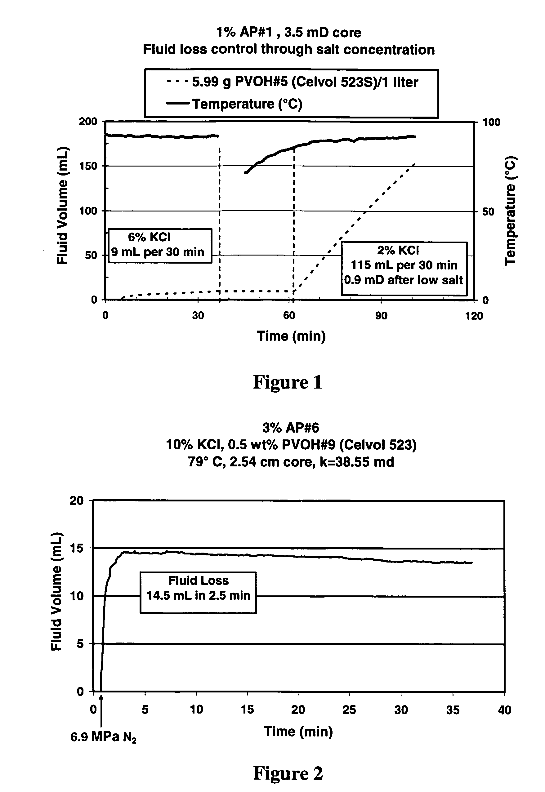
[0028]In the present invention, a dissolvable polymer is used in a well treatment fluid in a solid form under conditions where the polymer is not dissolved, and after the polymer has fulfilled its solid-form function, it is subsequently dissolved by altering conditions such as temperature or salinity to activate the polymer to fulfill a soluble-state function and / or to remove the polymer. A polyol such as polyvinyl alcohol (PVOH) is one example of a polymer having such utility. PVOH is a water-soluble synthetic polymer, which is available in many forms such as powder, granules, beads and fibers. The solubility of amorphous or partially crystalline PVOH in aqueous solution is a function of temperature and salinity. Controlling these parameters enables the use of PVOH as a fluid loss control agent and as a temporary formation seal, for example. PVOH at some concentrations forms a thick, highly viscous paste at high salinity, while at low salinity it dissolves completely. Thus, putting the fluid in place at high salinity provides the amorphous consistency of PVOH to temporarily seal and control fluid losses. The clean-up mechanism of the formation seal is based on the solubilization of PVOH in a low salinity environment, e.g. fresh water, 2% KCl, or the like.
[0029]The present invention also discloses a non-damaging drilling fluid composition that is based on surfactants and a polyol fluid loss control agent, which provides ease and flexibility for subsequent completion processes.
[0040]If desired, the downhole placement of the polyol particles is on a permeable formation surface to inhibit fluid loss to the formation. The polyol dissolution step may be used to at least partially restore permeability to the formation surface.

Problems solved by technology

When placing fluids in oilfield applications, fluid loss into the formation is a major concern.
Fluid loss reduces the efficiency of the fluid placement with respect to time, fluid volume, and equipment.
Such applications are those in which, without a filter cake, fluid would leak off into porous rock at an undesirable rate during a well treatment.
Typically, after these treatments have been completed the continued presence of the filter cake is undesirable or unacceptable.
The overall drilling / completion strategy based on polymer fluids is often operationally cumbersome, can lack long-term stability, can employ corrosive chemicals, and / or can be prone to cause formation damage.
High permeability formations are frequently poorly consolidated, so that sand control is needed.
This can sometimes be accomplished in the wellbore but normally cannot be done in a proppant or gravel pack.
However, these methods require fluid flow and often result in slow or incomplete filter cake removal.
Sometimes a breaker can be incorporated in the filter cake but these must normally be delayed (for example by esterification or encapsulation) and they are often expensive and / or difficult to place and / or difficult to trigger.
This technique, sometimes called a “water-frac” involves using extremely low polymer concentrations, so low that they cannot be effectively crosslinked, throughout the job.
This alternative has a major drawback: since there is inadequate viscosity to carry much proppant, high pump rates must be used and only very small concentrations of proppant (pounds mass proppant added per gallon of fluid (“PPA”)) can be used.
VES's are popular because they leave very clean proppant or gravel packs, but they do not form a filter cake by themselves.
VES fluids without fluid loss additives do not form filter cakes as a result of leak-off.
Fluid loss control may not always be optimal with VES systems, especially in higher permeability formations.
On the other hand, polymers have two major deficiencies: a) the filter cake, if left in place, can impede subsequent flow of hydrocarbons into the fracture and then into the wellbore, and b) polymer or crosslinked polymer will be left in the fracture itself, impeding or cutting off flow, either by physically blocking the flow path through the proppant pack or by leaving a high viscosity fluid in the fracture.
They are easier to use because they require fewer components and less surface equipment, but they may be less efficient (in terms of fluid loss) than polymers, depending upon the formation permeability and the specific VES system.
The poor performance of these conventional fluid loss additives is typically attributed to the period of high leak-off (spurt) before a filter cake is formed and to the formation of a filter cake permeable to the VES-based fluid.
Disturbance of the charge balance, due for instance to removing water, changing the pH or adding salt or water-miscible organic solvent, causes the colloidal particles to aggregate, resulting in the formation of a gel.
Further, degradation products of such materials have been shown to cause delayed breaking of polymer-viscosified fracturing fluids.
Since VES fluid systems cause negligible damage, it would be desirable to use a fluid loss additive that is compatible with the VES system and also causes negligible damage.
However, these fluid loss additive materials, as commercially obtained, often contain small amounts of acid or they start to hydrolyze to form acids when the fluids are first mixed or injected.
The concentrated polymer hinders fluid flow in the fracture and often results in underperforming fractures.
In addition, while low pH may break borate crosslinks, it is less effective for breaking the commonly used zirconium and titanium crosslinked gels.

Method used


Image

  • Well treatment with dissolvable polymer
  • Well treatment with dissolvable polymer
  • Well treatment with dissolvable polymer

Examples


examples

[0142]In the examples below, the following fluid formulations, PVOH's and other materials are used:

Fluid Formulations

[0143]AP#1—Surfactant Concentrate:

[0144]

Chemical CompositionWeight %Propane-1,2-diol13.4Propan-2-ol20.4Water5.1(Z)-13 Docosenyl-N-N-bis(2-Hydroxyethyl) Methyl61.1Ammonium Chloride

[0145]AP#2—Salt-Tolerant Fracturing Fluid:

[0146]A salt tolerant fracturing fluid specially modified to be made with fresh water and to be made with low guar concentrations and low crosslinker concentrations. Contains 3 g / L (25 ppt) guar, 20 g / L (167 ppt) potassium chloride, and 2.5 mL / L (2.5 gpt) of a borate crosslinker. The borate crosslinker is an 85:15 blend containing 85% of a 20-30% glycerol solution, 10-20% sodium tetraborate decahydrate, and 60-70% water, and 15% of a solution of 30% aqueous sodium hydroxide.

[0147]AP#3—Surfactant Concentrate:

[0148]

Chemical CompositionWeight %Urea2-3Propane-1,2-diol8Isopropanol11-12Ammonium Nitrate3Water29Quaternary Ammonium Compound10-30Quaternary Ammo...


PUM

PropertyMeasurementUnit
sizeaaaaaaaaaa
sizeaaaaaaaaaa
lengthaaaaaaaaaa

Abstract

Well treatment is disclosed that includes injecting a well treatment fluid with insoluble polyol polymer such as polyvinyl alcohol (PVOH) dispersed therein, depositing the insoluble polymer in the wellbore or an adjacent formation, and thereafter dissolving the polymer by reducing salinity and / or increasing temperature conditions in the environment of the polymer deposit. The method is disclosed for filter cake formation, fluid loss control, drilling, hydraulic fracturing and fiber assisted transport, where removal of the polyol at the end of treatment or after treatment is desired. The method is also disclosed for providing dissolved polyol as a delayed breaker in crosslinked polymer viscosified systems and viscoelastic surfactant systems. Also disclosed are well treatment fluids containing insoluble amorphous or at least partially crystalline polyol, and a PVOH fiber composition wherein the fibers are stabilized from dissolution by salinity.

Description

CROSS REFERENCE TO RELATED APPLICATIONS[0001]This invention is a continuation-in-part of U.S. patent application Ser. No. 11 / 159,023, filed Jun. 22, 2005 now U.S. Pat. No. 7,219,731, which claims the benefit of U.S. Provisional Patent Application Ser. No. 60 / 584,995, filed on Jul. 2, 2004; and U.S. patent application Ser. No. 11 / 159,023 is also a CIP of U.S. patent application Ser. No. 10 / 707,022, filed Nov. 14, 2003 now U.S. Pat. No. 7,066,260.FIELD OF THE INVENTION[0002]The invention relates to the treatment of oil and gas wells, more particularly to treatment methods and fluids utilizing a polymer that is at least partially insoluble in the treatment fluid during injection into the well and can be solubilized downhole for activation, inactivation or other functional modulation in the well treatment.BACKGROUND OF THE INVENTION[0003]In a wide range of well and formation treatment methods it is desirable to use various materials such as solids for downhole operations or procedures, ...

Claims


Application Information

Patent Timeline
Patent Type & Authority Patents(United States)
IPC IPC(8): E21B43/267E21B21/00E21B43/22C09K8/035C09K8/80
CPCC09K8/12C09K8/506C09K8/5083C09K8/512C09K8/516C09K8/68C09K8/70C09K8/80C09K8/52C09K2208/08C09K2208/26
Inventor HOEFER, ANN M. W.SULLIVAN, PHILIP F.SALAMAT, GOLCHEHREHBONEY, CURTIS L.LEE, JESSE C.CHEN, YIYANWILLBERG, DEAN M.BULOVA, MARINAFREDD, CHRISTOPHER N.BASER, BELGINPOPE, TIMOTHY L.
Owner SCHLUMBERGER TECH CORP
Why Eureka
Try Eureka