Apparatus and method for determining at least one electromagnetic quantity

a technology of apparatus, applied in the field of apparatus and method for determining at least one electromagnetic quantity, can solve the problems of inconvenient preparation of electrodes, inconvenient measurement, and inability to accurately determine electromagnetic quantities, etc., to achieve rapid and reliable determination of electromagnetic quantities, not very time-consuming, and easy to attach electrodes.

Inactive Publication Date: 2012-05-24
KONINKLIJKE PHILIPS ELECTRONICS NV
View PDF3 Cites 14 Cited by
  • Summary
  • Abstract
  • Description
  • Claims
  • Application Information

AI Technical Summary

Benefits of technology

[0038]According to another embodiment, the determination unit is adapted for determining the electromagnetic quantity depending on a quotient formed with the first and the second particle distribution quantity. This is an easy, not very time-consuming measure for reliably extracting the amount of the second particle distribution quantity representing the field distortion effects needed for determining the electromagnetic quantity.
[0039]In a preferred embodiment the two sub-zones take up first positions in space along a first trajectory corresponding to the first drive field frequency and second positions in space along a second trajectory corresponding to the second drive field frequency, wherein the control unit is adapted for controlling the drive field signal generator unit so that the first positions and the second positions substantially correspond to each other. The advantage of this measure is that influences arising from different positions in space the two sub-zones and therefore the field free point could take up conducting the first and the second measurement are eliminated. Hence, a very precise determination of the electromagnetic quantity is possible.
[0040]According to a further embodiment, the determination unit is adapted for determining an actual magnetic field strength quantity depending on the first and the second particle distribution quantity for determining the electromagnetic quantity. This measure represents a very easy approach for determining an electromagnetic quantity rapidly and reliably. The particle distribution quantity characterizes the spatial distribution of the magnetic particles within at least a portion of the object to be examined. Therefore, with using said particle distribution quantity an actual magnetic field strength quantity representing a magnetic field to which the portion of the body is exposed can be determined very precisely. Said actual magnetic field strength quantity can be used as a quantity for easily and reliably determining an electromagnetic quantity or for determining an intermediate quantity that in turn is the basis for determining an electromagnetic quantity, as for such a determination Maxwell equations can be applied. Advantageously the actual magnetic field strength quantity represents the magnetic field resulting from a superimposition of the magnetic selection field and the magnetic drive field showing the second drive field frequency. Said resulting magnetic field is also referred to as applied magnetic field. If present, a further field component exists, resulting from a magnetic focus field. The shape of the resulting magnetic field corresponds to the shape usually occurring at a standard MPI measurement.
[0041]According to another embodiment, the determination unit is adapted for determining the actual magnetic field strength quantity depending on a reference magnetic field strength quantity. With this measure the actual magnetic field strength can be determined in a very easy and reliable manner, as no detailed information about the geometry and the electric properties of the object to be examined is needed. Advantageously the reference magnetic field strength quantity describes the magnetic field resulting from superimposition of the magnetic selection field and the magnetic drive field showing the first drive field frequency. As considering the magnetic drive field showing the first drive field frequency, the reference magnetic field strength quantity can be easily derived from the geometry of the drive field coils and from the selection field coils using Biot-Savarts law.

Problems solved by technology

A great disadvantage of this method is the enormous amount of time needed for attaching the electrodes.
There is also the fact that the spatial resolution is not very high.
Although the amount of time needed for doing preparations before a measurement can be conducted is comparatively small, the use of this method is restricted because of the following disadvantages: Firstly, the frequency of the excitation electro-magnetic field is fixed to the so-called Larmor frequency of the MR system involved, with this frequency being significantly higher than the frequencies required for the majority of corresponding investigations.
Secondly, as it is impossible to rotate the excitation electro-magnetic field with a MR system, an anisotropy of the electric conductivity can be investigated only for very few, partially “rotatable” body parts like hands, feet, and head.
Thirdly, a MR scanner is a rather expensive imaging modality, particularly since for EPT it is “just” used to generate and measure magnetic fields.
As yet MPI apparatuses and methods are not adapted for determining electromagnetic quantities.

Method used


Image

  • Apparatus and method for determining at least one electromagnetic quantity
  • Apparatus and method for determining at least one electromagnetic quantity
  • Apparatus and method for determining at least one electromagnetic quantity

Examples


Embodiment Construction

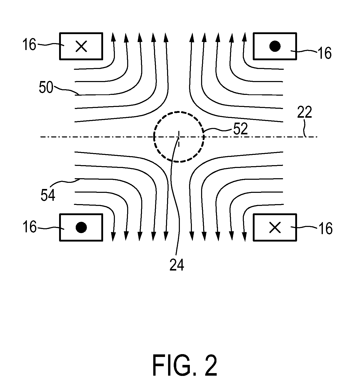
[0055]Before the details of the present invention shall be explained, basics of magnetic particle imaging shall be explained in detail with reference to FIGS. 1 to 4. In particular, two embodiments of an MPI scanner for medical diagnostics will be described. An informal description of the data acquisition is also given. The similarities and differences between the two embodiments will be pointed out.

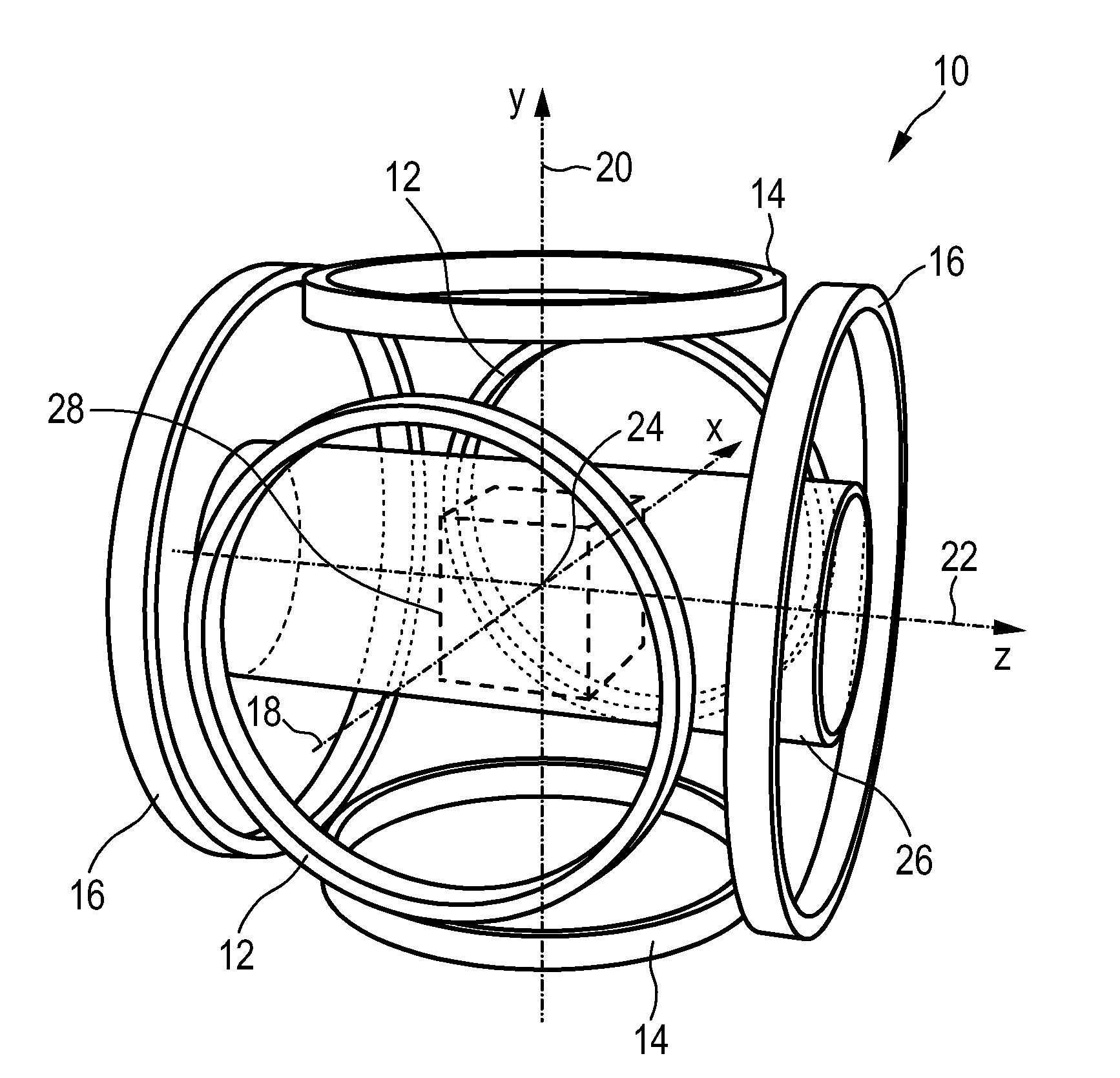
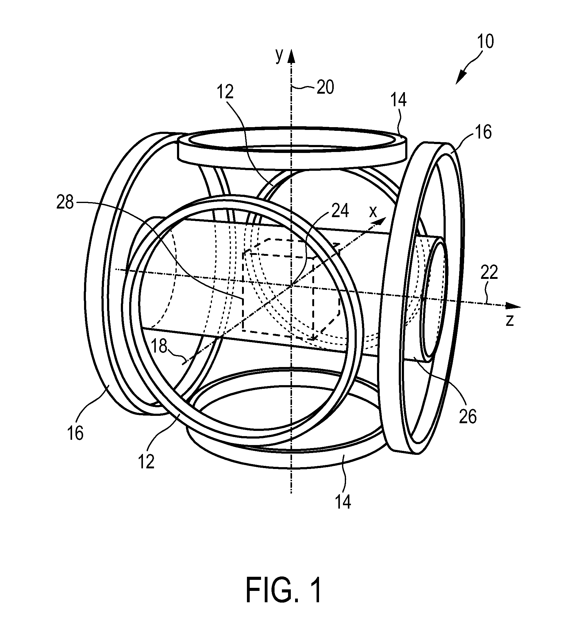
[0056]The first embodiment 10 of an MPI scanner shown in FIG. 1 has three prominent pairs 12, 14, 16 of coaxial parallel circular coils, each pair being arranged as illustrated in FIG. 1. These coil pairs 12, 14, 16 serve to generate the selection field as well as the drive and focus fields. The axes 18, 20, 22 of the three coil pairs 12, 14, 16 are mutually orthogonal and meet in a single point, designated the isocenter 24 of the MPI scanner 10. In addition, these axes 18, 20, 22 serve as the axes of a 3D Cartesian x-y-z coordinate system attached to the isocenter 24. The vertical axis ...


PUM

PropertyMeasurementUnit
MRI frequenciesaaaaaaaaaa
frequencyaaaaaaaaaa
frequencyaaaaaaaaaa

Abstract

The present invention relates to an apparatus (100) for determining at least one electromagnetic quantity characterizing an electromagnetic property of an object, in particular a human body, wherein said object contains magnetic particles. The apparatus (100) applying the known principle of Magnetic Particle Imaging (MPI) comprises selection means for generating a magnetic selection field (50) having the known field pattern showing a field free point (FFP), drive means for changing the position in space of the FFP by means of a magnetic drive field, receiving means for acquiring detection signals depending on the magnetization of the magnetic particles within a field of view (28) and a reconstruction unit (152) for reconstructing a particle distribution quantity depending on the detection signals. The apparatus (100) further comprises a control unit (150) for controlling the receiving means for acquiring a first set of detection signals corresponding to a first drive field frequency and a second set of detection signals corresponding to a second drive field frequency, with both drive field frequencies differing from each other. The control unit (15) further controls the reconstruction unit (152) for reconstructing a first particle distribution quantity depending on the first set of detection signals and a second particle distribution quantity depending on the second set of detection signals. The apparatus (100) further comprises a determination unit (160) for determining the electromagnetic quantity depending on the first and second particle distribution quantity. The present invention further relates to a corresponding method as well as to a computer program.

Description

FIELD OF THE INVENTION[0001]The present invention relates to an apparatus and a corresponding method for determining at least one electromagnetic quantity. Further, the present invention relates to a computer program for implementing said method on a computer and for controlling such an apparatus.BACKGROUND OF THE INVENTION[0002]In medical imaging, biological tissue properties are used to produce image contrasts. For example the electrical conductivity differs for different types of tissue. Therefore a conductivity quantity characterizing the conductivity distribution throughout at least a portion of a human body is significant for distinguishing different tissues of a human body. For instance, said conductivity quantity can be used to distinguish between tumours and healthy tissue or between necrotic and vital tissue after a myocardial infarction. Said conductivity quantity can also be used to support the characterization of brain tissue in connection with stroke or cerebral haemor...

Claims


Application Information

Patent Timeline
Patent Type & Authority Applications(United States)
IPC IPC(8): G01N27/72
CPCA61B5/05A61B2562/0223A61B5/7221A61B5/0515
Inventor VERNICKEL, PETERKATSCHER, ULRICHGLEICH, BERNHARDRAHMER, JURGEN ERWIN
Owner KONINKLIJKE PHILIPS ELECTRONICS NV
Why Eureka
Try Eureka