System and method for sample dilution and particle imaging

a particle imaging and sample technology, applied in the field of fluid analysis systems, can solve the problems of time-consuming and relatively expensive evaluation process itself, and achieve the effect of efficient and cost-effectiv

Inactive Publication Date: 2014-05-29
FLUID IMAGING TECH
View PDF5 Cites 13 Cited by
  • Summary
  • Abstract
  • Description
  • Claims
  • Application Information

AI Technical Summary

Benefits of technology

[0005]It is an object of the present invention to provide a system and related method to enable the analysis of the contents of a fluid, particularly a fluid with high solids content. It is also an object of the present invention to provide a system and related method that provides an efficient and cost-effective way for conditioning the fluid to enable observation of particles contained within the flu...

Problems solved by technology

Unfortunately, these tools and these types of fluids require considerable time to condition the fluid sufficiently t...

Method used


Image

  • System and method for sample dilution and particle imaging
  • System and method for sample dilution and particle imaging
  • System and method for sample dilution and particle imaging

Examples


Embodiment Construction

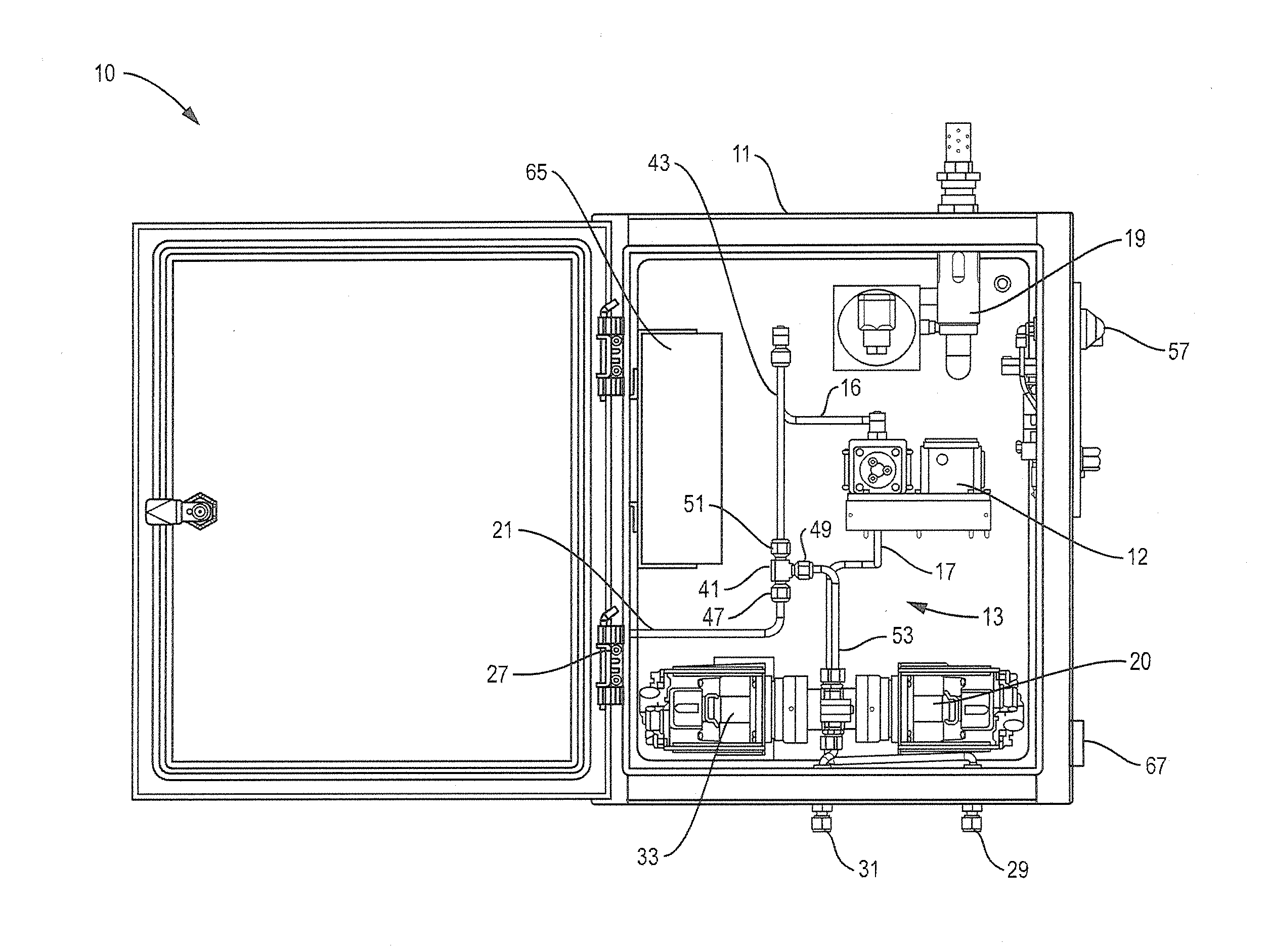
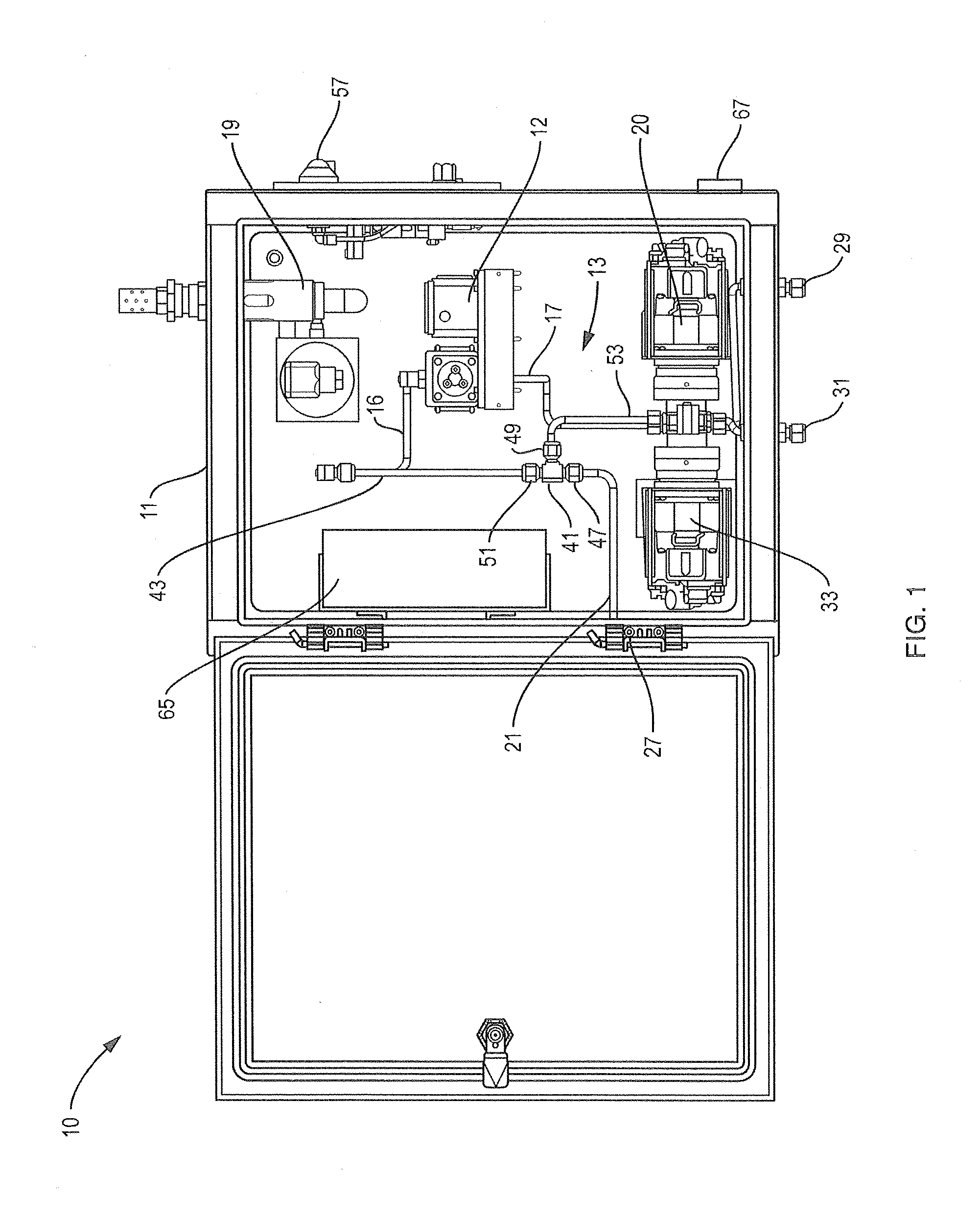
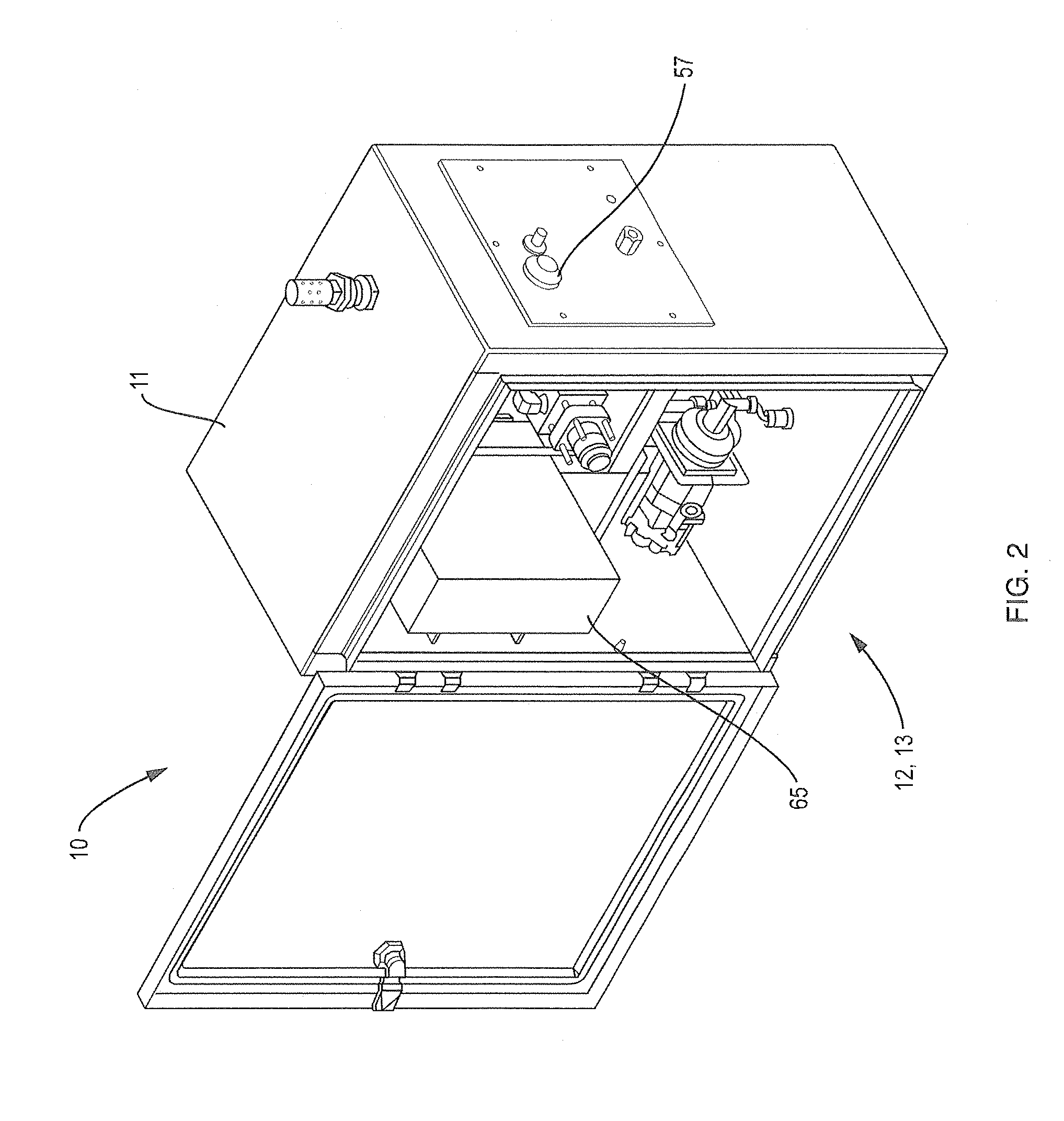
[0017]A system 10 of the present invention suitable for diluting a fluid, as necessary, and enabling the generation of high quality automated imaging of particles that exist in a fluid is shown in FIGS. 1 and 2. The system 10 includes an optional containment box 11, a fluid dilution system 13, a particle imaging system 12, an optional cooling element 19 and a computing device 65. The containment box may be weather tight so that the system 10 may be deployed to a remote location for automated sample, for example, wherein data are collected and either processed onsite and the results transmitted to a different location, or the data may be transmitted to a different location for processing. The computing device 65 forms part of the fluid dilution system 13 and the particle imaging system 12 and may be embodied in a single computing device as represented herein or as two separate computing device, one for each of systems 13 and 12, wherein the two computing devices in that embodiment ar...


PUM


Abstract

A system for diluting a sample fluid sufficiently to enable the capture images of particles contained in the sample fluid. The system includes a fluid dilution system and a particle imaging system. The fluid dilution system includes a mixing conduit for combining a diluent and the sample solution. The mixing conduit is coupled to a flow chamber associated with imaging capturing devices including a camera. When the sample fluid is too opaque or viscous to enable capture of particle images of sufficient clarity, the fluid dilution system is activated to introduce diluent into the mixing conduit in sufficient volume to dilute the sample fluid. The diluted sample fluid is passed through the flow chamber and particle images captured. Information regarding captured images may be stored, analyzed and transferred from a remote location.

Description

FIELD OF THE INVENTION[0001]The present invention relates generally to systems for analyzing fluids. More particularly, the present invention relates to systems and methods for modifying such fluids to enable the observation of the contents of the fluid, including obtaining images of particles within the fluid. Still more particularly, the present invention relates to fluid dilution systems and methods coupled with particle imaging activities.BACKGROUND OF THE INVENTION[0002]Various optical / flow systems employed for transporting a fluid within an analytical instrument to an imaging and optical analysis area exist in the art. A liquid sample is typically delivered into the bore of a chamber and the sample is interrogated in some way so as to generate analytical information concerning the nature or properties of the sample. The sample may be stagnant or flowing. In one arrangement, a light source may be directed to the chamber to illuminate its contents. One or more photographs may be...

Claims


Application Information

Patent Timeline
IPC IPC(8): H04N7/18
CPCG01N21/53H04N7/18
Inventor DUPLISEA, MATTHEWDRAKE, CORIEIDE, MASON
Owner FLUID IMAGING TECH
Why Eureka
Try Eureka