
Asphalt pavement pore water pressure simulation test device and method

A technology of pore water pressure and simulation testing, which is applied in the fields of measuring devices, permeability/surface area analysis, suspension and porous material analysis, etc., which can solve the difficulties in actual operation, the fluctuation of pore water pressure on the pavement lasts for a short time, and it is difficult to ensure that the pores do not change Problems such as water flow, to achieve the effect of increasing the loading speed

Inactive Publication Date: 2018-03-27
广州市和富市政工程有限公司
View PDF8 Cites 0 Cited by
  • Summary
  • Abstract
  • Description
  • Claims
  • Application Information

AI Technical Summary

Problems solved by technology

Due to the complexity and concealment of the internal pore structure of asphalt concrete, it is difficult to ensure that the connected pores are drilled and the pore water flow is not changed when drilling holes in the specimen for the installation of sensors.
It is necessary to drill holes in the asphalt concrete specimens to install sensors and ensure that the drilled holes communicate with the connected pores, install the sensors firmly, and lead the sensor data lines through the pressure vessel to the data acquisition instrument. This is practically necessary. very difficult
On the other hand, due to the fast speed of the vehicle, the time to pass the road is very short, and the pore water pressure fluctuation of the road surface lasts very short. If a high-frequency pressure monitoring and acquisition system is not used, it is difficult to accurately capture the fluctuation information. High-frequency pressure acquisition systems are also required when short-term loads are applied in model tests

Method used


Image

  • Asphalt pavement pore water pressure simulation test device and method
  • Asphalt pavement pore water pressure simulation test device and method
  • Asphalt pavement pore water pressure simulation test device and method

Examples


Embodiment 1

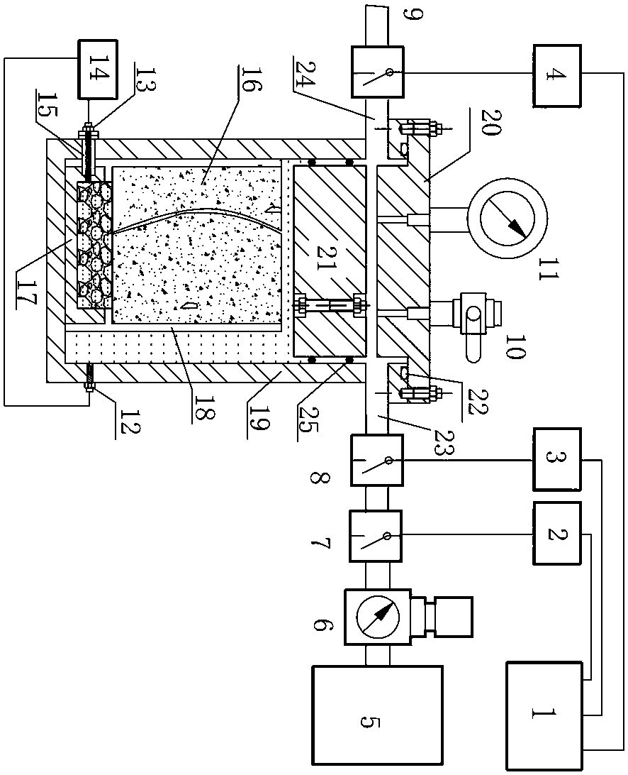
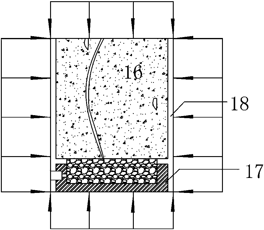
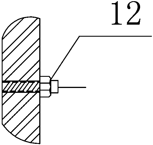
[0050] like Figure 1~4 Shown, a kind of asphalt pavement pore water pressure simulation testing device comprises asphalt concrete specimen 16, open container 17, pressure vessel 19, and asphalt concrete specimen 16 and open vessel 17 are positioned at pressure vessel 19, and the asphalt concrete specimen 16 Adhesive 18 is filled between the bottom and the opening annular part of the open container 17 (the adhesive 18 used in this embodiment is specifically epoxy resin, and phenolic resin can also achieve the same technical effect), and the asphalt concrete specimen 16 The side wall of the open container 17 is coated with an adhesive 18 for sealing, and the lower part of the side wall of the open container 17 is symmetrically provided with two mounting holes, one of which is provided with a first pressure sensor for measuring the external water pressure of the asphalt concrete specimen 16 12. Another mounting hole is provided with a second pressure sensor 13 for measuring the ...

Embodiment 2

[0058] like Figure 5 As shown, the specific process of the method for testing using the device described in Embodiment 1 is as follows:

[0059] (1) An asphalt concrete specimen 16 with a diameter of not less than 100mm and not more than 155mm is obtained by indoor preparation or on-site core drilling on the road surface. The height of the asphalt concrete specimen 16 in this embodiment is 150mm;

[0060] (2) Fill the cylindrical open container 17 with the same outer diameter as the asphalt concrete specimen 16 and with a sensor installation hole on one side with crushed stones sieved by a standard square hole sieve of 13.2 mm to 16 mm, and then fill it with water;

[0061] (3) Glue the bottom of the asphalt concrete specimen 16 and the top open circular part of the cylindrical opening container 17 filled with gravel with adhesive 18, and coat the circumference of the side wall of the asphalt concrete specimen 16 with adhesive 18 and make it flow naturally until the adhesive...

Embodiment 3

[0074] The specific process of the method for testing using the device described in Embodiment 1 is the same as in Embodiment 2, except that the control process adopted in this embodiment is as follows:

[0075] The programmable controller 1 controls the first air intake control valve 7 to open for 0.25s, and controls the second air intake control valve 8 to open for 0.25s at 0.15s, that is, the first air intake control valve 7 and the second air intake Apply pressure to the water and the test piece within 0.1s while the control valve 8 is simultaneously opened; at 0.25s, the control valve 9 is opened for 1s to exhaust to atmospheric pressure; thereby applying instantaneous external water pressure to the asphalt concrete test piece 16 to simulate the asphalt pavement Pore ​​water flow and corresponding pore water pressure.

[0076] Table 2 Example 3 control flow schedule

[0077]  

0s

0.15s

0.25s

0.4s

1.25s

The first air intake control valve 7

...


PUM


Abstract

The invention discloses a simulation testing device and method for bituminous pavement pore water pressure. The device comprises a bituminous concrete sample, an open container and a pressure container, wherein the bituminous concrete sample and the open container are located in the pressure container, the portion between the bottom of the bituminous concrete sample and the opening annular portion of the open container is filled with a bonding agent, the side wall of the bituminous concrete sample is coated with the bonding agent, a first pressure sensor used for measuring outer water pressure of the bituminous concrete sample and a second pressure sensor used for measuring bottom water pressure of the bituminous concrete sample are arranged on the side wall of the open container. The method includes the steps that after the prepared bituminous concrete sample and the open container are placed in the pressure container, the pressure sensors, a piston and a seal pressure container are installed, a control flow path is selected to start testing, and data of the pressure sensors is collected. Directional movement of pore water is achieved through the device, and the response regularity of dynamically-changed bituminous concrete pore water pressure under the external water pressure action can be tested.

Description

technical field [0001] The invention relates to the analysis of dynamic water pressure of asphalt pavement, in particular to a simulating test device and method for pore water pressure of asphalt pavement. Background technique [0002] The dynamic water pressure on asphalt pavement has a great destructive effect on the pavement. However, there are few studies on the actual change law of the pore water pressure at different moments of the wheel load process under different wheel load combinations, different pavement pore types, and different pavement depths. , that is, the actual conditions that cause hydrodynamic pressure are not fully considered, so the research conclusions cannot be mutually verified. Air-free water is incompressible, and its elastic modulus is very large. After unloading, the stress in the water should dissipate instantly. However, existing theoretical studies regard the pores of asphalt pavement as water-saturated state, but it is concluded that the pore...

Claims


Application Information

Patent Timeline
Patent Type & Authority Patents(China)
IPC IPC(8): G01N15/08
CPCG01N15/0826
Inventor 姜旺恒周兴韦潇树关宏信周志刚
Owner 广州市和富市政工程有限公司
Learn More