
Tunnel image splicing method and system

A splicing system and tunnel technology, which is applied in the field of tunnel scene images, can solve problems such as the inability to meet the data volume tunnel image splicing requirements, and the inability to complete tunnel splicing.

Active Publication Date: 2016-05-04
WUHAN WUDA ZOYON SCI & TECH
View PDF3 Cites 30 Cited by
  • Summary
  • Abstract
  • Description
  • Claims
  • Application Information

AI Technical Summary

Problems solved by technology

Only using a method based on feature point matching such as SIFT cannot complete the stitching of the entire tunnel, and cannot meet the requirements of tunnel image stitching with a huge amount of data
[0005] In order to ensure the high resolution of tunnel images, different cameras and different focal lengths are used to collect tunnel images. Therefore, the tunnel images to be stitched include images taken by many different cameras and lenses with different focal lengths. big challenge

Method used


Image

  • Tunnel image splicing method and system
  • Tunnel image splicing method and system
  • Tunnel image splicing method and system

Examples


Embodiment Construction

[0054] In order to make the object, technical solution and advantages of the present invention clearer, the present invention will be further described in detail below in conjunction with the embodiments and with reference to the accompanying drawings. It should be understood that these descriptions are exemplary only, and are not intended to limit the scope of the present invention.

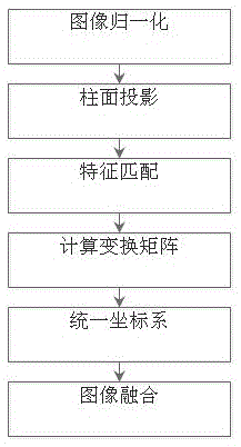
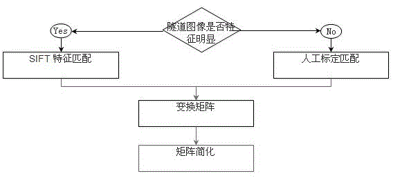
[0055] The invention is a fast mosaic method of tunnel images based on the combination of feature point matching and artificial point feature point matching. The specific implementation steps are as figure 1 As shown, the implementation process of the embodiment can be summarized as the following steps, and the specific implementation of each step is as follows:

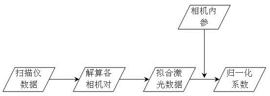
[0056] Step 1: Normalize the image, based on the data from the laser scanner, according to the relative positional relationship between the camera and the scanner obtained in advance, calculate the object distance corresponding to eac...


PUM


Abstract

The invention provides a tunnel image splicing method and a tunnel image splicing system; the method and the system are used for carrying out splicing on an image collected by each camera in a tunnel image collection system; the tunnel image collection system comprises multiple cameras and a laser scanner; when carrying out the splicing on the tunnel images obtained by all cameras via single exposure on a certain section, the method comprises the following steps: working out an object distance corresponding to each of the cameras based on data of the laser scanner, carrying out normalization processing on the image collected by each camera, projecting all to-be-spliced images to a cylindrical surface, adopting SIFT (Scale Invariant Feature Transform) characteristic matching and obtaining matching points, calculating an initial transformation matrix, simplifying and extracting translation parameters to obtain a final transformation matrix among images, unifying a coordinate system, and fusing the images to obtain the splicing reconstructed smooth seamless tunnel image. The technical scheme disclosed by the invention has the advantages of fast splicing speed, relatively high splicing precision, high robustness, strong practicability and the like, and is convenient for subsequent tunnel disease detection.

Description

technical field [0001] The invention belongs to the technical field of computer vision, in particular to the technical field of tunnel image splicing, which can acquire tunnel scene images with a large viewing angle. Background technique [0002] Since the tunnel lining section is generally relatively large, in order to achieve relatively high crack detection accuracy, multiple area array cameras must be used to cover the surface of the tunnel lining. There will be a certain overlap area between every two cameras. In order to visually display the diseases of the tunnel lining surface, it is necessary to stitch the image data of multiple area array cameras. That is, several images with overlapping parts and different viewing angles are combined into a large seamless high-resolution image. [0003] Tunnel image stitching is to register and fuse multiple overlapping images of the same section of the tunnel at the same time, and stitch them into a large field of view picture i...

Claims


Application Information

Patent Timeline
IPC IPC(8): G06T3/40
CPCG06T3/4038G06T2207/10004G06T2207/20221G06T3/12
Inventor 李清泉曹民
Owner WUHAN WUDA ZOYON SCI & TECH
Learn More