Radio frequency antenna device and mobile terminal

A technology of radio frequency antenna and dielectric antenna, applied in the directions of antenna support/installation device, slot antenna, radiating element structure, etc., can solve the problem of poor performance of mobile terminal antenna, improve the transceiver performance, improve compatibility, and increase the structure the effect of strength

Inactive Publication Date: 2016-05-04
YULONG COMPUTER TELECOMM SCI (SHENZHEN) CO LTD
View PDF4 Cites 10 Cited by
  • Summary
  • Abstract
  • Description
  • Claims
  • Application Information

AI Technical Summary

Problems solved by technology

It can solve the problem of poor performance of mobile

Method used


Image

  • Radio frequency antenna device and mobile terminal
  • Radio frequency antenna device and mobile terminal
  • Radio frequency antenna device and mobile terminal

Examples


Embodiment Construction

[0025] The following will clearly and completely describe the technical solutions in the embodiments of the present invention with reference to the accompanying drawings in the embodiments of the present invention. Obviously, the described embodiments are only some, not all, embodiments of the present invention. Based on the embodiments of the present invention, all other embodiments obtained by persons of ordinary skill in the art without creative efforts fall within the protection scope of the present invention.

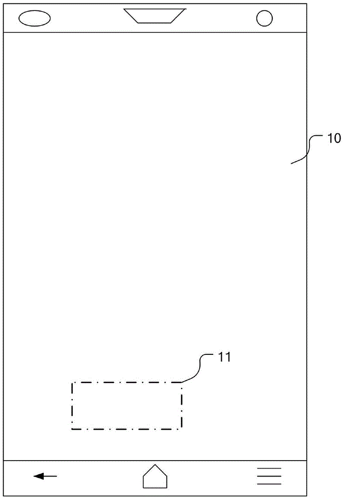
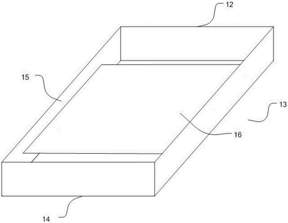
[0026] see Figure 1-Figure 4 , is a structural diagram of a radio frequency antenna device provided by an embodiment of the present invention. In the embodiment of the present invention, the radio frequency antenna device 1 includes: a metal middle frame, a metal back cover 17 , a dielectric antenna 11 and a liquid crystal display 10 . The metal middle frame includes a top frame 12, a bottom frame 14, a left frame 15 and a right frame 13. The two ends of the top f...


PUM


Abstract

The embodiment of the invention discloses a radio frequency antenna device, which comprises a closed metal middle frame free of a breakpoint, a metal back cover, a transparent dielectric antenna and a liquid crystal display screen LCD, wherein the metal middle frame comprises two side frames, a top frame and a bottom frame, which are connected into a frame form; two ends of the top frame are connected to the top ends of the two side frames respectively; two ends of the bottom frame are connected to the bottom ends of the two side frames respectively; the metal middle frame is combined with the metal back cover to form a cavity; the liquid crystal display screen is arranged in the cavity; the dielectric antenna is buried into the upper surface of a glass substrate of the liquid crystal display screen; the dielectric antenna and the upper surface of the glass substrate are coplanar; a feed terminal of the dielectric antenna is electrically connected with a radio frequency circuit in the cavity; and a ground terminal of the dielectric antenna is grounded. The embodiment of the invention further discloses a mobile terminal. By the radio frequency antenna device and the mobile terminal, the antenna performance of the mobile terminal with a metal housing can be improved.

Description

technical field [0001] The invention relates to the field of antennas, in particular to a radio frequency antenna device and a mobile terminal. Background technique [0002] With the continuous improvement of users' requirements for the appearance of mobile terminals, more and more mobile terminals with metal appearance appear on the market, which leads to further deterioration of the electromagnetic environment inside the mobile terminal. The current antenna structure used by mobile terminals is: the metal middle frame is a closed structure, and the gap formed between the metal plate and the metal middle frame is used to effectively radiate electromagnetic energy. [0003] The problems of the current antenna structure are: it is necessary to design a complex feed structure to match the slot antenna; when it is necessary to adjust the resonant frequency of the slot antenna, it is realized by changing the size of the slot, and the adjustment is not flexible enough, and the ra...

Claims


Application Information

Patent Timeline
IPC IPC(8): H01Q1/22H01Q1/38H01Q13/10
CPCH01Q13/10H01Q1/22H01Q1/38
Inventor 张超
Owner YULONG COMPUTER TELECOMM SCI (SHENZHEN) CO LTD
Why Eureka
Try Eureka