Novel carbon brush structure

A carbon brush, a new type of technology, applied in the direction of collectors, electrical components, rotating collectors, etc., can solve the problems of unfavorable collector ring heat dissipation, different wear speeds of carbon brushes, short-circuit accidents, etc., to facilitate daily inspection and maintenance, Prevents uneven stress and increases service life

Inactive Publication Date: 2016-05-04
宁波市镇海路石建筑科技有限公司
View PDF0 Cites 1 Cited by
  • Summary
  • Abstract
  • Description
  • Claims
  • Application Information

AI Technical Summary

Problems solved by technology

[0002] A carbon brush is a device that transmits energy or signals between the fixed part and the rotating part of a motor or generator or other rotating machinery. It is generally made of pure carbon and a coagulant. There is a spring to press it tightly on the rotating shaft. Some carbon brushes have a simple structure, and the wire is directly pressed tightly by the copper head. Due to the large vibration force generated by the mechanical rotation, it is easy to fall off, and the service life of the carbon brush is short. In view of this, There is a plan to weld the carbon brush body and the copper sheet to both ends of the wire respectively, and because the connection is too strong, once it falls off, the equipment can only be replaced again, which is too expensive
[0003] In addition, when multiple carbon brushes are squeezed and controlled by the elastic element, the elastic force of the elastic element is not the same, which often leads to different wear speeds of different carbon brushes, which is easy to cause failure, and the dust generated by the wear during work may pollute the power generation unit, and may cause short-circuit accidents in the live parts of the unit. Therefore, the dust must be collected. The conventional method is to cover the outer side of the entire collector ring and all carbon brushes with a dust collection cover made of insulating material, and place them in the A number of dust collection holes are opened around the dust collection hood, and then connected to the vacuum cleaner through pipelines. This method is not conducive to the heat dissipation of the collector ring due to poor ventilation, and there are potential safety hazards. In addition, the carbon brush inspection and replacement of this scheme is troublesome.

Method used


Image

  • Novel carbon brush structure

Examples


Embodiment Construction

[0018] The specific implementation manners of the present invention will be further described below in conjunction with the accompanying drawings, so as to make the technical solution of the present invention easier to understand and grasp.

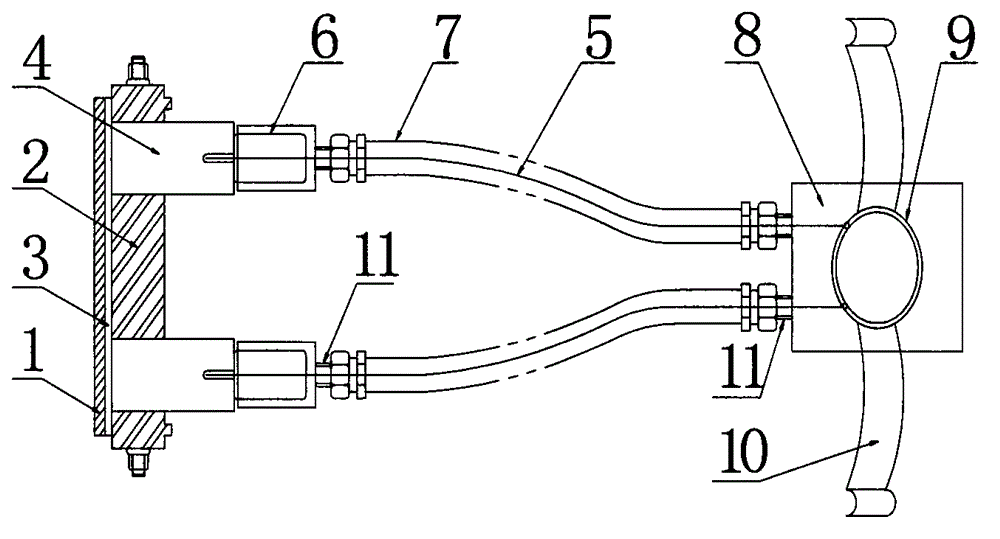
[0019] Such as figure 1 As shown, a new carbon brush structure includes a carbon brush base 1, a carbon brush tube base 2 fixed on the carbon brush base 1, and a carbon brush body 4 installed in the carbon brush tube base 2. The carbon brush tube The seat 2 is dumbbell-shaped, and a number of carbon brush tubes corresponding to the size and shape of the carbon brush body 4 are evenly distributed therein. The carbon brush tubes are all on the same plane. Elastic support 3.

[0020] Inside the carbon brush body 4 there is a lead wire 5, the wire 5 is a copper core flexible wire, the two ends of the wire 5 are respectively designed as bolts, one end is screwed into the screw hole inside the carbon brush body 4, and the other end is passed t...


PUM


Abstract

Provided in the invention is a novel carbon brush structure. The structure is formed by a carbon brush pedestal, a carbon brush pipe seat fixed on the carbon brush pedestal, and carbon brush bodies installed in the carbon brush pipe seat. An elastic support element is arranged between the carbon brush pipe seat and the carbon brush pedestal. Leading-put wires are arranged inside the carbon brush bodies; and one end of each wire is connected with one carbon brush body by a bolt and the other end is connected with a copper sheet cap arranged on the surface of a dust-removing distribution device. Elastic flexible insulating tubes sleeve the peripheries of the wires; and one end of each elastic flexible insulating tube is connected with the dust-removing distribution device and the other end is connected with an insulating dust-removing box connected to one side of each carbon brush body. On the basis of the structure, wire shedding can be prevented; and the service life is long. Moreover, the extrusion force applied on each carbon brush is identical and thus a fault can be avoided; and the dust collection effect is good and the maintenance becomes convenient.

Description

technical field [0001] The present invention relates to a carbon brush structure, in particular to a new type of carbon brush structure for small household appliances, which belongs to "H01R" in the International Patent Classification: electrical conduction connection; a structural combination of a group of mutually insulated electrical connection elements; connection device; Collectors" technical field. Background technique [0002] A carbon brush is a device that transmits energy or signals between the fixed part and the rotating part of a motor or generator or other rotating machinery. It is generally made of pure carbon and a coagulant. There is a spring to press it tightly on the rotating shaft. Some carbon brushes have a simple structure, and the wire is directly pressed tightly by the copper head. Due to the large vibration force generated by the mechanical rotation, it is easy to fall off, and the service life of the carbon brush is short. In view of this, There is ...

Claims


Application Information

Patent Timeline
Patent Type & Authority Applications(China)
IPC IPC(8): H01R39/36H01R39/415H01R39/02
Inventor 卢杰
Owner 宁波市镇海路石建筑科技有限公司
Why Eureka
Try Eureka