Differential protection method for partition inverse-time transformer by considering DC bias effects

A technology of differential protection and DC bias, applied to emergency protection circuit devices, electrical components, etc., can solve problems such as current transformer waveform distortion

Inactive Publication Date: 2016-05-04
NORTH CHINA ELECTRIC POWER UNIV (BAODING)
View PDF5 Cites 9 Cited by
  • Summary
  • Abstract
  • Description
  • Claims
  • Application Information

AI Technical Summary

Problems solved by technology

On the other hand, after the external fault is removed, the primary side current of the current transformer returns to the load current, and its demagnetization effect is not enough to make the magnetic flux of the current transformer core exit the saturation section, so it may still operate in the local hysteresis near the saturation point In the loop, the waveform of the primary and secondary sides of the current transformer is slightly distorted, so that the differential current is just greater than the minimum operating current of the ratio braking characteristic. At this time, the braking current is approximately equal to the load current, and it is easy to fall into the action of the ratio braking characteristic. in the district

Method used


Image

  • Differential protection method for partition inverse-time transformer by considering DC bias effects
  • Differential protection method for partition inverse-time transformer by considering DC bias effects
  • Differential protection method for partition inverse-time transformer by considering DC bias effects

Examples


Embodiment Construction

[0039] The technical solutions of the present invention will be further described in detail below in conjunction with the accompanying drawings and specific embodiments.

[0040] A method that takes into account the influence of DC bias on differential protection of transformers, in particular, prevents misoperation of differential protection due to the combined action of DC bias and non-periodic components of fault current to accelerate current transformer saturation when an out-of-area fault occurs in the transformer, At the same time, it avoids the new method of misoperation after the external fault is removed.

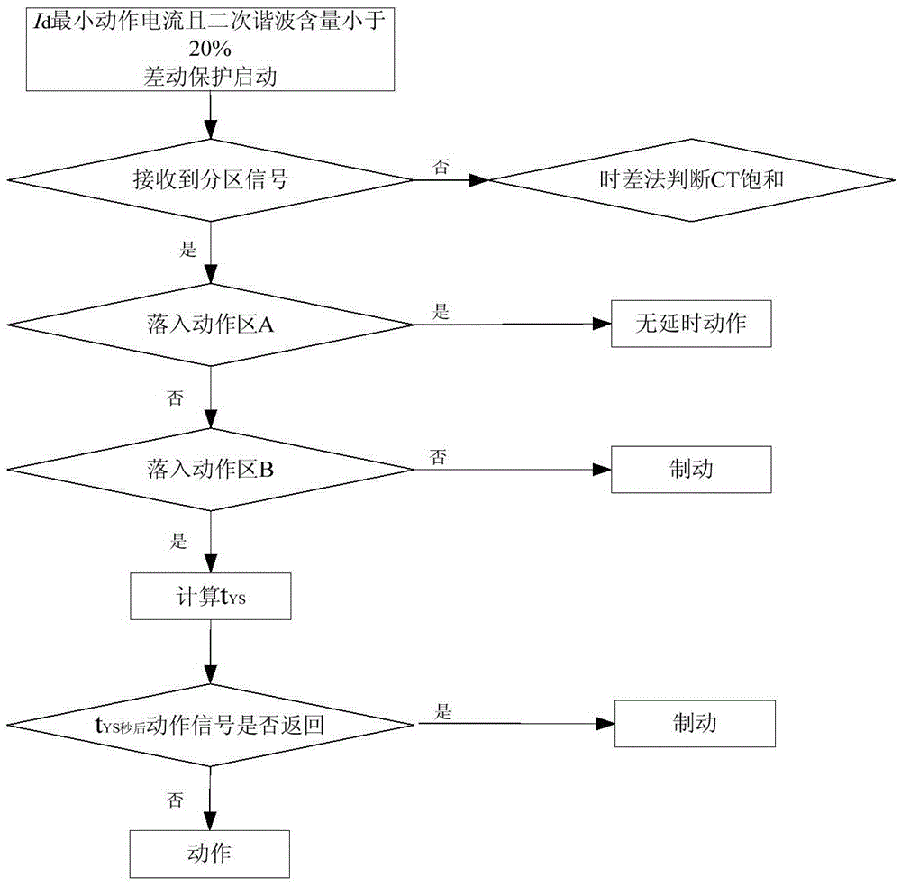
[0041] Such as figure 1 Shown is a flow chart of a new method for subregional inverse time transformer differential protection considering the influence of DC bias proposed by the present invention. The method includes the following steps:

[0042] (1) Assume that the sampling frequency of the microcomputer protection device is 1200Hz, and collect the DC current v...


PUM


Abstract

The invention belongs to the technical field of relay protection of power systems, and particularly relates to a differential protection method for a partition inverse-time transformer by considering DC bias effects. The method is characterized by comprising the following steps: judging whether a partition signal is sent out or not by detecting a DC of a neutral point; if a microprocessor protection device does not receive the signal, judging an internal fault or an external fault according to an original ratio braking characteristic, judging saturation of a current transformer by a time-difference method and blocking the external fault; if the signal is received, partitioning an action region of the ratio braking characteristic into two blocks, if a serious internal fault is generated, enabling the signal to drop into a no-delay action region and if a light internal fault is generated, enabling the signal to drop into an inverse-time action region; and if the external fault is generated, enabling the current transformer to quickly retreat from the inverse-time action region, returning an action instruction within a time delay, retreating and entering a brake region and blocking differential protection. After the fault is removed, a brake current is a load current; the minimum action current of the ratio braking characteristics is lifted on the basis of the partition signal; and a relatively high differential current after the fault is removed is evaded.

Description

technical field [0001] The invention belongs to the technical field of electric power system relay protection, and in particular relates to a method for differential protection of partitioned inverse time transformers considering the influence of DC bias. Background technique [0002] my country's AC-DC interconnected EHV / UHV grid is currently under construction. DC transmission plays an important role in the development of my country's power grid with its unique technical advantages. At present, several high-voltage DC transmission projects have been put into operation in China. However, the adoption of DC transmission technology has had a certain impact on the conventional AC power grid and its equipment. When the DC power transmission system adopts a single-pole ground loop operation mode, the DC in the ground flows into the AC grid through the grounded neutral point of the transformer, which will cause DC bias. The magnetic phenomenon has a great impact on the safe and s...

Claims


Application Information

Patent Timeline
IPC IPC(8): H02H7/045
CPCH02H7/0455
Inventor 郑涛陆格野黄婷刘连光
Owner NORTH CHINA ELECTRIC POWER UNIV (BAODING)
Why Eureka
Try Eureka