Synchronous reluctance motor rotor and synchronous reluctance motor

A technology for synchronous reluctance motors and rotors, applied in the direction of magnetic circuit rotating parts, magnetic circuits, electrical components, etc., can solve the problems of performance degradation, motor salient pole difference reduction, etc., to improve magnetic flux leakage, increase motor output, and improve The effect of motor performance

Active Publication Date: 2016-05-04
ZHUHAI GREE REFRIGERATION TECH CENT OF ENERGY SAVING & ENVIRONMENTAL PROTECTION
View PDF6 Cites 12 Cited by
  • Summary
  • Abstract
  • Description
  • Claims
  • Application Information

AI Technical Summary

Problems solved by technology

[0003] The existence of the bridge section 203 is to ensure that the rotor can still be mechanically integrated after the formation of each flux barrier 201 inside the rotor. figure 2 As shown by the magnetic force lines in the middle, part of the leakage flux is directly short-circuited through the bridge section, rather than figure 1 The main magnetic circuit (effective magnetic field line) shown by the dotted line in the middle passes through the magnetic conduction channel 202 of the rotor, resulting in a decrease in the salient pole difference of the motor, resulting in a decrease in performance

Method used


Image

  • Synchronous reluctance motor rotor and synchronous reluctance motor
  • Synchronous reluctance motor rotor and synchronous reluctance motor
  • Synchronous reluctance motor rotor and synchronous reluctance motor

Examples


Embodiment Construction

[0030] The present invention is described below based on examples, but the present invention is not limited to these examples. In the following detailed description of the invention, some specific details are set forth in detail. The present invention can be fully understood by those skilled in the art without the description of these detailed parts. To avoid obscuring the essence of the present invention, well-known methods, procedures, procedures, and components have not been described in detail.

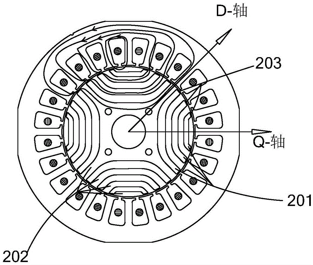
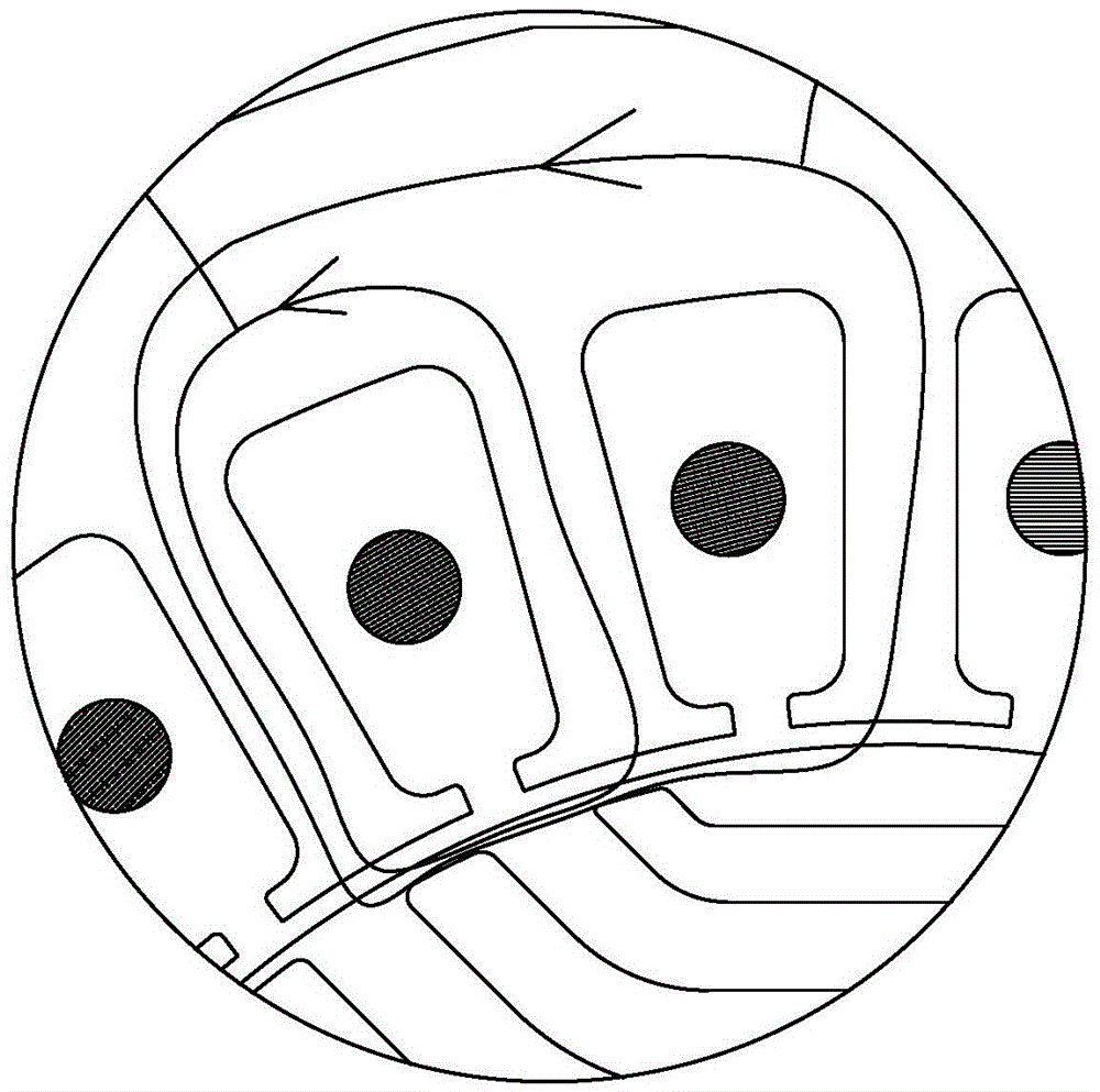
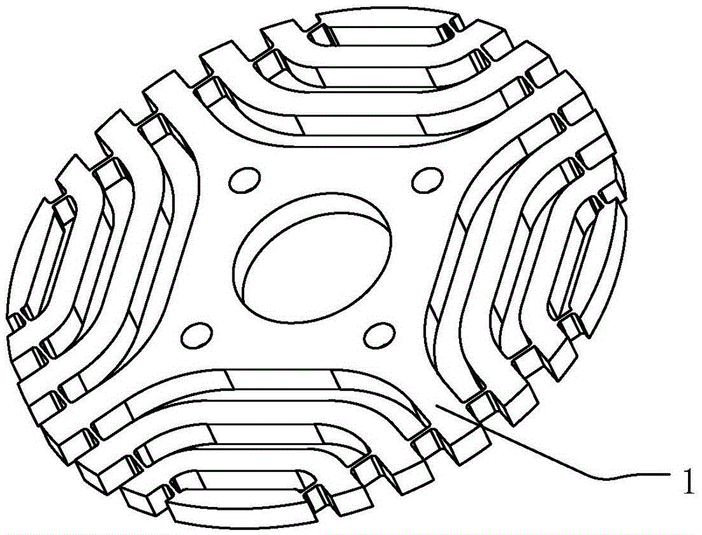
[0031] The following combination Figure 3-6 The rotor structure of the synchronous reluctance motor in the first embodiment of the present invention is described in detail, as Figure 5 As shown in , the rotor core 1 is included, and the rotor core 1 includes a plurality of flux barrier groups 11 . Each flux barrier group 11 includes at least two flux barriers arranged at intervals in the radial direction of the rotor core 1, a magnetic conduction channel is provided between a...


PUM


Abstract

The invention aims at providing a synchronous reluctance motor rotor and a synchronous reluctance motor, and mainly aims to solve the problem of relatively serious magnetic leakage of a conventional rotor. The synchronous reluctance motor rotor comprises a rotor iron core, wherein a plurality of magnetic flux barrier groups are arranged on the rotor iron core, each magnetic flux barrier group comprises at least two magnetic flux barriers, the at least two magnetic flux barriers are arranged in a radial direction of the rotor iron core at intervals, the synchronous reluctance motor rotor is characterized that the magnetic flux barriers extend to the outer edge of the rotor iron core, an opening is formed at the outer edge of the rotor iron core, the rotor iron core also comprises magnetic bridges, the magnetic bridges are arranged inside the magnetic flux barriers and used for connecting the inner surfaces and the outer surfaces of the magnetic flux barriers, and the distance between the magnetic bridges and the outer edge of the rotor iron core is not less than the predetermined distance. By the synchronous reluctance motor rotor, the magnetic leakage of the rotor can be reduced, and the rotor strength is improved.

Description

technical field [0001] The invention relates to the field of motors, in particular to a synchronous reluctance motor rotor and a synchronous reluctance motor. Background technique [0002] In the prior art solution, the publication number is CN101230856A, which discloses a motor rotor structure, and its structure is as follows: figure 1 As shown in: the motor includes a stator and a rotor, the stator and the rotor slices both adopt a laminated structure, wherein the rotor slices contain a plurality of flux barriers 201 formed therein, for each flux barrier 201, from the outer circumferential surface of the rotor The distances to the ends of the flux barriers 201 are basically the same, and for different flux barriers 201, the distances between the ends of the flux barriers 201 and the outer circumferential surface of the rotor are different; The obvious feature of the rotor is that the outer surface is circular, and the bridge section 203 connecting the inner and outer surf...

Claims


Application Information

Patent Timeline
Patent Type & Authority Applications(China)
IPC IPC(8): H02K1/22H02K1/28
CPCH02K1/22H02K1/28H02K1/246H02K2213/03
Inventor 童童胡余生陈彬卢素华
Owner ZHUHAI GREE REFRIGERATION TECH CENT OF ENERGY SAVING & ENVIRONMENTAL PROTECTION
Why Eureka
Try Eureka