A Zero-Voltage Switching High-Gain DC-DC Converter Containing Switched Capacitors

A zero-voltage switching and switching capacitor technology, applied in the field of DC-DC conversion, can solve the problems of reducing the efficiency of the converter, low circuit efficiency, increasing operating loss, etc., to solve the problem of switching loss, no energy loss components, reduce voltage effect of stress

Inactive Publication Date: 2018-03-23
XIAMEN UNIV
View PDF5 Cites 1 Cited by
  • Summary
  • Abstract
  • Description
  • Claims
  • Application Information

AI Technical Summary

Problems solved by technology

In order to obtain high voltage gain at low duty cycle, a converter using cascaded boost topology is proposed, but its control method is complicated and the circuit efficiency is low
In order to simplify the control method and improve the circuit efficiency, a high-gain step-up DC converter with a pumping capacitor is proposed, but compared with the traditional Boost converter, there is one more switch tube, and the switch tube has a voltage spike problem. Large loss
However, the scheme of using coupled inductors to build a high-gain converter achieves a large voltage gain, but the connection of coupled inductors leads to more operating modes of the converter and complicated control. At the same time, leakage inductance will cause large Shut-off voltage spikes, resulting in increased operating losses and reduced converter efficiency

Method used


Image

  • A Zero-Voltage Switching High-Gain DC-DC Converter Containing Switched Capacitors
  • A Zero-Voltage Switching High-Gain DC-DC Converter Containing Switched Capacitors
  • A Zero-Voltage Switching High-Gain DC-DC Converter Containing Switched Capacitors

Examples


Embodiment Construction

[0021] The present invention will be further described below by means of the accompanying drawings and examples.

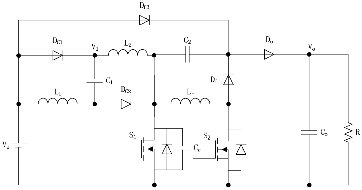
[0022] see figure 1 , the embodiment of the present invention includes a power switch tube (S 1 ), two power inductors (L 1 , L 2 ), two switched capacitors (C 1 、C 2 ), three clamping diodes (D C1 、D C2 、D C3 ), a resonant capacitor (C r ), a resonant inductor (L r ), an auxiliary switching tube (S 2 ), a freewheeling diode (D f ), an output diode (D o ) and an output capacitor (C o ). The first power inductor (L 1 ) to one end of the power supply (V i ) anode, the first clamping diode (D C1 ) anode and the third clamping diode (D C3 ) connected to the anode; the first power inductor (L 1 ) and the other end of the second clamping diode (D C2 ) of the anode and the first switched capacitor (C 1 ) connected to one end; the first switched capacitor (C 1 ) and the other end of the first clamping diode (D C1 ) of the cathode and the second power...


PUM


Abstract

A zero-voltage switch high-gain DC-DC converter with switched capacitors relates to DC-DC conversion. Including power supply, power switching tube, power inductor, switching capacitor, clamping diode, freewheeling diode, output diode and output capacitor; one end of the first power inductor is connected to the positive pole of the power supply, the anode of the first clamping diode and the anode of the third clamping diode The other end of the first power inductor is connected to the anode of the second clamping diode and one end of the first switch capacitor; the other end of the first switch capacitor is connected to the cathode of the first clamping diode and one end of the second power inductor, and the other end of the second power inductor It is connected to the cathode of the second clamping diode, the drain of the power switch tube and one end of the second switching capacitor; the other end of the second switching capacitor is connected to the cathode of the third clamping diode, the cathode of the freewheeling diode and the anode of the output diode; the cathode of the output diode is connected to the One end of the output capacitor is connected, and the other end of the output capacitor is connected together with the negative pole of the power supply and the source pole of the power switch tube.

Description

technical field [0001] The invention relates to DC-DC conversion, in particular to a zero-voltage switching high-gain DC-DC converter with switched capacitors. Background technique [0002] With the increasingly serious problems of global energy shortage and environmental pollution, solar photovoltaic power generation has become an emerging industry that is widely concerned and focused on development because of its clean, safe, convenient, and high-efficiency characteristics. In recent years, solar photovoltaic power generation technology has achieved unprecedented development, and solar photovoltaic grid-connected power generation has become one of the main ways of solar energy utilization. Research on photovoltaic grid-connected power generation technology has great practical significance to alleviate the energy crisis, protect the ecological environment and ensure the sustainable development of the economy. Generally speaking, the output voltages of photovoltaic panels, ...

Claims


Application Information

Patent Timeline
Patent Type & Authority Patents(China)
IPC IPC(8): H02M3/07H02M1/32
CPCH02M1/32H02M3/07H02M1/325Y02B70/10
Inventor 何良宗郑智鹏
Owner XIAMEN UNIV
Why Eureka
Try Eureka