
Mobile terminal radio frequency front-end and mobile terminal

A radio frequency front-end and mobile terminal technology, applied in the direction of electrical components, transmission systems, etc., can solve the problems of large number of components, degradation of radio frequency performance, interference, etc., and achieve the effect of improving radio frequency performance and reducing interference

Active Publication Date: 2016-05-04
DONGGUAN COOLPAD SOFTWARE TECH
View PDF4 Cites 34 Cited by
  • Summary
  • Abstract
  • Description
  • Claims
  • Application Information

AI Technical Summary

Problems solved by technology

It can solve the problem of the large number of antennas and components inside the mobile terminal in the prior art, causing serious interference and degradation of radio frequency performance

Method used


Image

  • Mobile terminal radio frequency front-end and mobile terminal

Examples


Embodiment Construction

[0025] The following will clearly and completely describe the technical solutions in the embodiments of the present invention with reference to the accompanying drawings in the embodiments of the present invention. Obviously, the described embodiments are only some, not all, embodiments of the present invention. Based on the embodiments of the present invention, all other embodiments obtained by persons of ordinary skill in the art without creative efforts fall within the protection scope of the present invention.

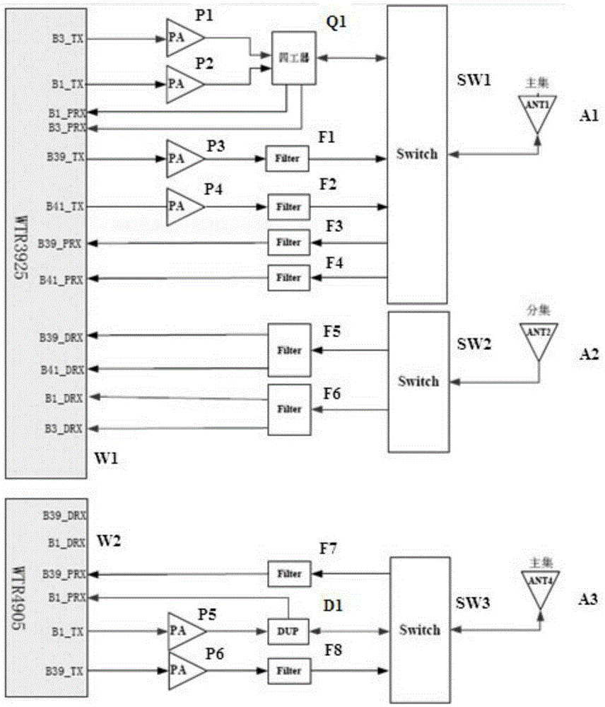
[0026] see figure 1 , is a schematic structural diagram of a radio frequency front end of a mobile terminal provided by an embodiment of the present invention. In an embodiment of the present invention, the radio frequency front end includes:

[0027] The first main antenna A1, the diversity antenna A2, the second main antenna A3, the first filter F1, the second filter F2, the third filter F3, the fourth filter F4, the fifth filter F5, the sixth Filter F6, seventh...


PUM


Abstract

The embodiment of the invention discloses a mobile terminal radio frequency front-end comprising a first main antenna, a diversity antenna, a second main antenna, a quadruplexer, a first filter, a second filter, a third filter, a fourth filter, a fifth filter, a sixth filter, a seventh filter, an eighth filter, a first power amplifier, a second power amplifier, a third power amplifier, a fourth power amplifier, a fifth power amplifier, a sixth power amplifier, a quadruplexer, a duplexer, a first radio frequency switch, a second radio frequency switch, a first RF transceiver, a second RF transceiver and a controller. The embodiment of the invention also discloses a mobile terminal. With application of the mobile terminal radio frequency front-end and the mobile terminal, the number of the antennas in the internal part of the mobile terminal can be reduced, and internal interference and complexity of the antenna design can be reduced.

Description

technical field [0001] The invention relates to the field of antennas, in particular to a radio frequency front end of a mobile terminal and the mobile terminal. Background technique [0002] In order to meet the requirements of single-user peak rate and system capacity improvement, the most direct method is to increase the system transmission bandwidth. The LTE-Advanced system proposes a carrier aggregation method to increase the transmission bandwidth. At present, most of the mobile terminals supporting carrier aggregation adopt Qualcomm's uplink 2CC and downlink 3CC carrier aggregation scheme, which needs to be realized by using 2 main antennas and 2 diversity antennas. [0003] Existing mobile terminals are becoming more and more light and thin, the internal space of mobile terminals is becoming smaller and smaller, and the electromagnetic environment is very complex. The existing 4-antenna carrier aggregation solution has too many antennas, which requires the layout of ...

Claims


Application Information

Patent Timeline
IPC IPC(8): H04B1/40
CPCH04B1/40
Inventor 王兵沈小波
Owner DONGGUAN COOLPAD SOFTWARE TECH
Learn More