Surgery fixture clip applier

A clip applier and fixture technology, which is applied in medical science, wound clips, surgery, etc., can solve problems such as uneven inference size, excessive speed, high dimensional accuracy, wear resistance, and high lubrication performance, so as to avoid sticking Hysteresis and extrusion deformation, the effect of improving stability

Active Publication Date: 2016-05-04
HANGZHOU OPTACLA MEDICAL INSTR
View PDF5 Cites 26 Cited by
  • Summary
  • Abstract
  • Description
  • Claims
  • Application Information

AI Technical Summary

Problems solved by technology

[0003] However, most of the existing clamping mechanisms use springs as the driving mechanism. Due to the uneven size, excessive speed and poor stability of the spring during the compression and release process
During the pushing process, surgical clips often fall off, become loose, and are squeezed into the machine during the pushing process, resulting in deformation, so that they cannot be clamped effectively or cannot be used
In the surgical operation process, the use of surgical clips needs to be accurate and timely. If the above problems occur, it will seriously affect the success of the operation.
Although surgical clip appliers with other precise structures can achieve the above-mentioned purpose, the internal mechanical structure of this type of clip feeding equipment is often extremely complicated. The push rod used for feeding is made of plastic, and its dimensional accuracy, durability The requirements for grinding performance and lubricating performance are extremely high, and the current technology is difficult to meet, resulting in high cost, so it cannot meet the needs of the market

Method used


Image

  • Surgery fixture clip applier
  • Surgery fixture clip applier
  • Surgery fixture clip applier

Examples


Embodiment 1

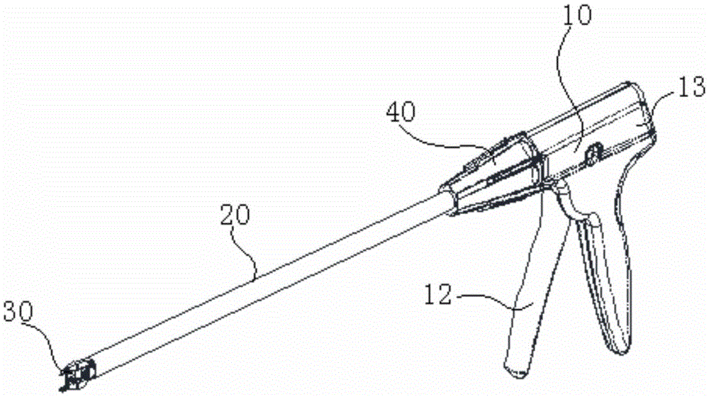
[0027] Please refer to figure 1 , a surgical clip applier provided in this embodiment includes a body 10, a pliers rod 20, a pliers mouth 30 and a clip pushing device (not shown in the figure). The body 10 includes a shell 13 and a trigger device (not shown) for driving the clamp pushing device. The trigger device is movably connected with the body 10. The trigger device has an actuated state and a released state. The trigger device includes a handle 12, which can be operated by operating the handle 12 can cause the trigger device to be in an actuated state. The pliers rod 20 extends from the shell 13 of the body 10. The body 10 can define an axial direction, and the pliers rod 20 can extend distally along the axial direction. The clamp mouth 30 of the surgical clamp, the clamp pushing device and the surgical clamp are accommodated in the hollow cavity of the forceps rod 20 (hereinafter referred to as the inner cavity of the forceps rod), the clamp pushing device is coupled t...

Embodiment 2

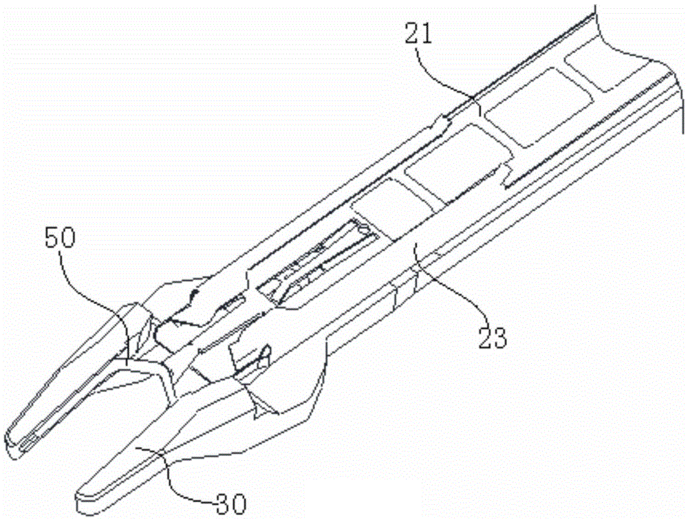
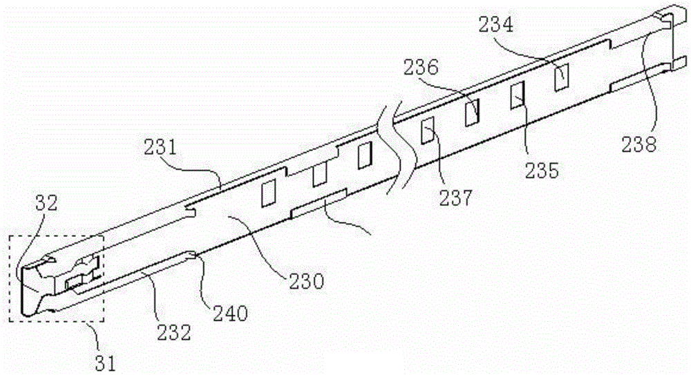
[0038] The difference between this embodiment and Embodiment 1 is that a waiting bin for fixing the clamp is provided at the farthest end where the track and the jaws are connected, such as image 3 with Figure 9 As shown, the top of the side wall 231 near the end of the pliers mouth 30 on the track 23 is bent inwardly to form a folded edge 232, so that the bottom surface 230 of the track, the side wall 231 and the folded edge 232 form a semi-closed slot-type waiting warehouse 31 . The semi-closed slot that constitutes the warehouse to be dispatched extends a certain distance to the rear, and the bottom surface 230 of the end flange 232 of the extension is tilted to form a guide 240, so that the front end of the bracket 21 slides into the warehouse to be dispatched. For the convenience of understanding, it is defined in this article that the direction along the axial direction of the pliers rod toward the pliers mouth is forward, and the direction toward the body is backward...


PUM


Abstract

A surgery fixture clip applier comprises: a body (10) which has a triggering device, the triggering device having an actuation state and a releasing state; a nippling lever (20) extending from the body and forming a twine hook (30) at the far end far away from the body; a track (23) being axially fixed at the inner cavity of the nippling lever along the nippling lever and extending to the twine hook; a bracket (21) sliding along the track, being capable of disposing at least one surgery fixture and being connected to the triggering device; a push plate (22) being arranged in the cavity formed between the bracket and the track and sliding matching the bracket, the push plate being abutted against the surgery fixture and being moving with the movement of the bracket and pushing the surgery fixture to the twine hook when being moving along the track to the twine hook, and when the bracket is returned to the body along the track, the push plate doing not return or return for a preset distance with the bracket and then stop returning. The surgery fixture clip applier is able to realize stable clip applying without deformation and stagnation, greatly reduce the technology requirement and reduce the cost.

Description

technical field [0001] The invention relates to the field of medical equipment, in particular to a surgical clip applier. Background technique [0002] During the existing surgical operation, surgical clamps are used to ligate some blood vessels, catheters, and other channels that need to be ligated, as well as human tissues. This kind of surgical clip is fired by a special surgical clip applier. A common surgical clip applier includes a shell with a trigger device, a slender rod connected to the shell, and a jaw at the end of the rod. . When in use, align the mouth of the pliers with the blood vessels and other tissues to be ligated, control the surgical clip applier to push the surgical clips to the mouth of the pliers, and then close the mouth of the pliers to deform the outer shell clamp, so as to achieve the ligation effect. [0003] And existing most clamping mechanism adopts spring as driving mechanism more, because the reasoning size in the spring compression relea...

Claims


Application Information

Patent Timeline
Patent Type & Authority Applications(China)
IPC IPC(8): A61B17/128
CPCA61B17/1285A61B2017/12004A61B17/128A61B17/1222A61B2017/00367A61B2017/00862
Inventor 谭任木王进
Owner HANGZHOU OPTACLA MEDICAL INSTR
Why Eureka
Try Eureka