Thermoelectric powered wireless vehicle system sensor system

A vehicle system and sensor technology, applied to vehicle components, battery circuit devices, thermoelectric devices that only use the Peltier or Seebeck effect, etc., can solve the problems of high cost and weight, reduce battery cost, reduce wiring complexity, Eliminates the effect of battery replacement

Active Publication Date: 2018-07-13
GM GLOBAL TECH OPERATIONS LLC
View PDF6 Cites 0 Cited by
  • Summary
  • Abstract
  • Description
  • Claims
  • Application Information

AI Technical Summary

Problems solved by technology

Traditional 12V direct current (DC) has relatively high cost and weight due to the wires and wiring in traditional electronic systems

Method used


Image

  • Thermoelectric powered wireless vehicle system sensor system
  • Thermoelectric powered wireless vehicle system sensor system
  • Thermoelectric powered wireless vehicle system sensor system

Examples


Embodiment Construction

[0060] As required, detailed embodiments of the present disclosure are disclosed herein. The disclosed embodiments are merely examples that can be implemented in different and alternative forms and combinations thereof. As used herein, terms such as "exemplary" and similar terms extend broadly to refer to an example that serves as an illustration, sample, model, or style.

[0061] As used herein, the term "vehicle" is not limited to automobiles. Although the present technology is primarily described herein in relation to automobiles, the present technology is not limited to automobiles. The principles can be used in a wider variety of applications, for example in relation to aircraft, ships and other vehicles.

[0062] vehicle

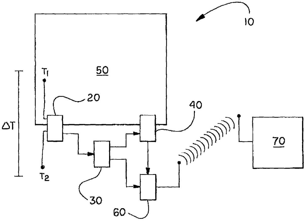
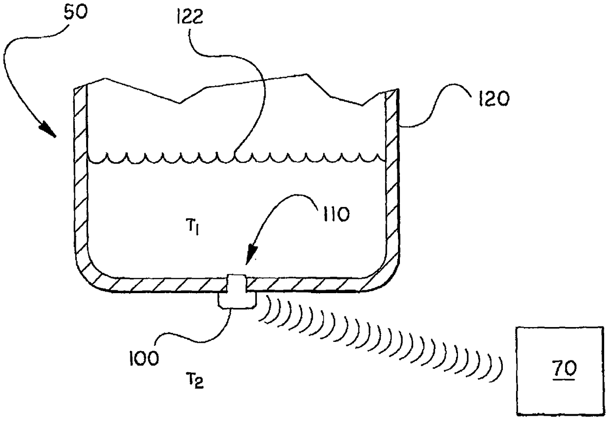
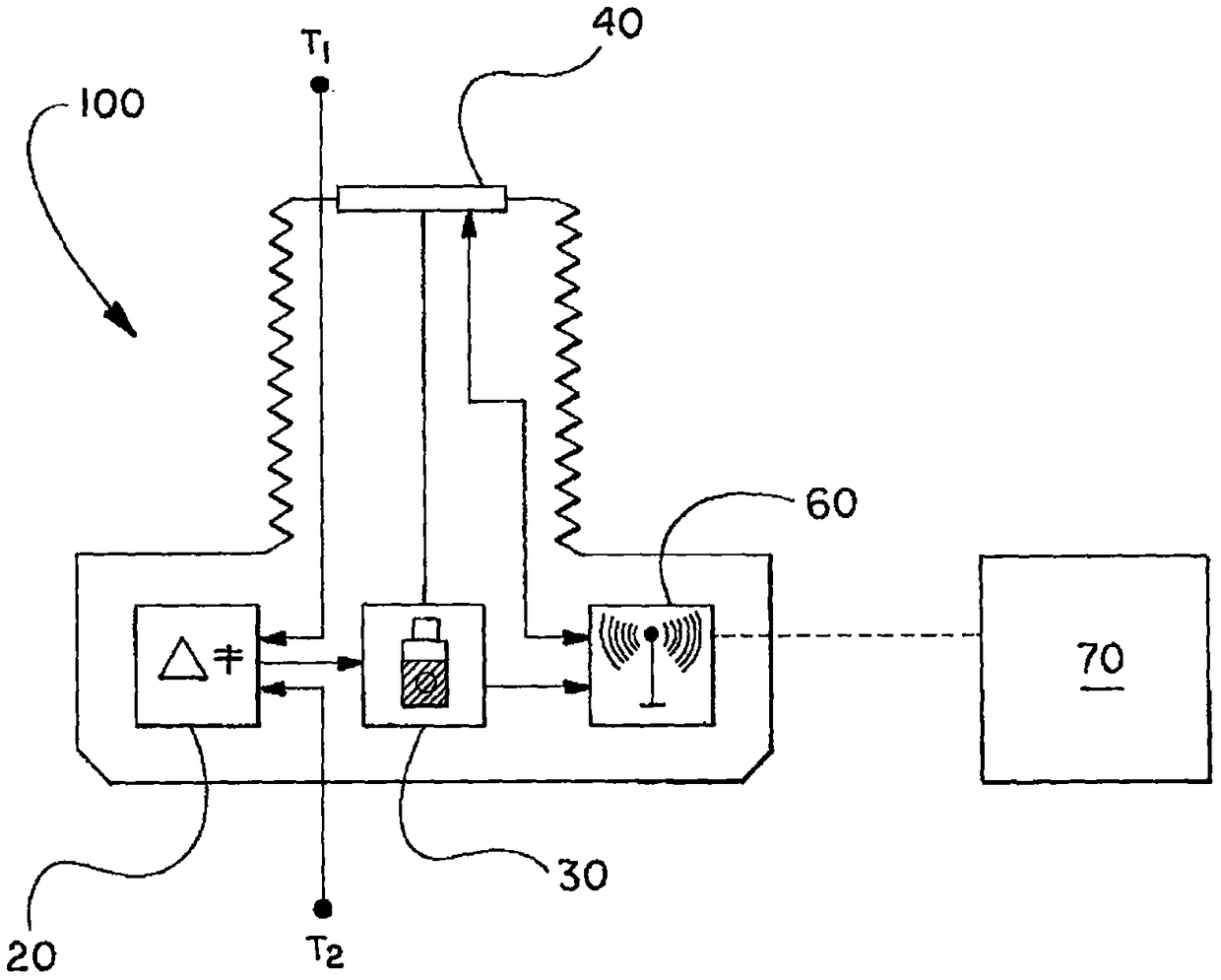
[0063] according to figure 1 In the illustrated embodiment, vehicle 10 includes heat harvesting device 20 , battery 30 , sensors 40 associated with vehicle systems 50 , wireless transmitter 60 , and computing unit 70 .

[0064] The thermoelectric ...


PUM


Abstract

The invention discloses a thermoelectrically powered wireless vehicle system sensor system. A vehicle including a heat harvesting device positioned adjacent to a heat generating vehicle system. The heat harvesting device generates electricity based on the temperature difference to power the sensors and wireless transmitters.

Description

technical field [0001] The present disclosure generally relates to thermoelectrically powered wireless vehicle system sensors. Background technique [0002] Vehicle system sensors are powered by batteries, piezoelectric, or conventional 12V direct current (DC). Batteries need periodic replacement. Piezoelectric collectors have low energy density, have relatively low efficiency, durability, and reliability and do not provide constant power. Conventional 12V direct current (DC) has relatively high cost and weight due to wires and wiring in conventional electronic systems. The wires carry power to and signals from the various sensors. Contents of the invention [0003] The technology relates to thermoelectrically powered wireless vehicle system sensors. This publication describes thermoelectric generators (TEGs), such as thermoelectric modules (TEMs), that provide power to sensors and wireless transmitters. [0004] The present invention includes following scheme: [00...

Claims


Application Information

Patent Timeline
Patent Type & Authority Patents(China)
IPC IPC(8): B60K15/06B60C23/04F01N5/02B60R16/023
CPCB60C23/04B60K15/06B60R16/0232F01N5/025G01F23/14G01N33/2852H02J50/00Y02T10/12G01F23/804H10N10/13H02J7/00
Inventor N·P·艾里什J·R·萨尔瓦多W·L·维莱尔
Owner GM GLOBAL TECH OPERATIONS LLC
Why Eureka
Try Eureka