Bearing feeding device

A feeding device and bearing technology, applied in conveyors, transportation and packaging, rotary conveyors, etc., can solve the problems of bulky feeding mechanism, unstable movement process, complex structure, etc., and achieve small size, simple and compact overall structure. , the effect of high degree of automation

Inactive Publication Date: 2016-05-11
HEFEI UNIV OF TECH
View PDF5 Cites 8 Cited by
  • Summary
  • Abstract
  • Description
  • Claims
  • Application Information

AI Technical Summary

Problems solved by technology

[0002] At present, many feeding devices have appeared on the market, and there are also some bearing feeding devices, but most of them use vibrating discs or cylinders to realize the feeding of bearings. Not stable, and not suitable for some small product assembly lines

Method used


Image

  • Bearing feeding device
  • Bearing feeding device
  • Bearing feeding device

Examples


Embodiment Construction

[0018] The embodiments of the present invention are described in detail below. This embodiment is implemented on the premise of the technical solution of the present invention, and detailed implementation methods and specific operating procedures are provided, but the protection scope of the present invention is not limited to the following implementation example.

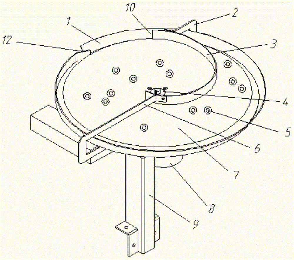
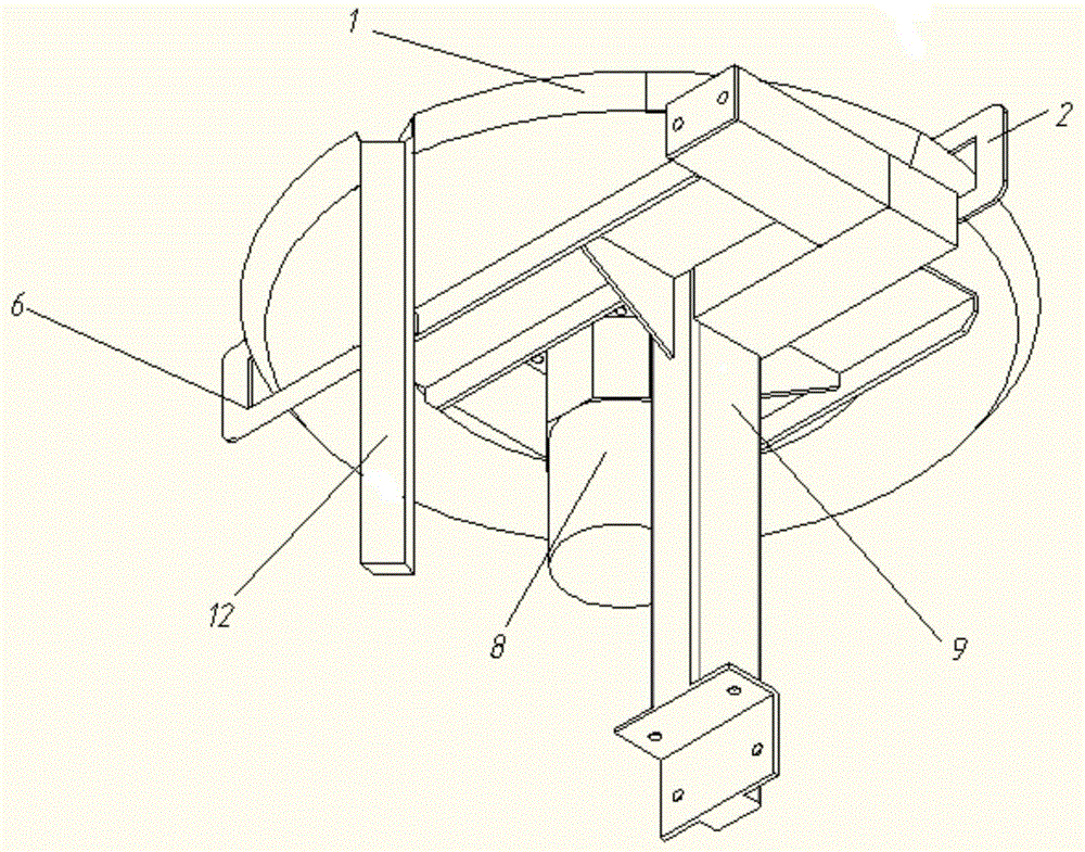
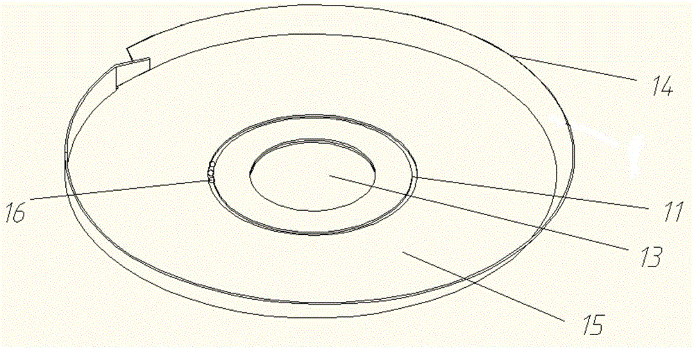
[0019] see Figure 1 to Figure 3 , this embodiment discloses a bearing feeding device, which includes a frame 9, on which a tray 1 is arranged, and the tray 1 includes a bottom plate 15 and a baffle 14 vertically arranged on the edge of the bottom plate, and a turntable is arranged on the bottom plate 15 for rotation 7. A turntable shaft 4 is fixedly arranged in the middle of the turntable 7, a perforation 13 is provided in the middle of the bottom plate, the turntable shaft 4 is located in the perforation 13 of the bottom plate, a motor 8 is provided under the tray 1, and the output shaft of the motor 8 is fixedly...


PUM


Abstract

The invention discloses a bearing feeding device. The bearing feeding device comprises a rack. A tray is arranged on the rack. The tray comprises a bottom plate and a baffle arranged at the edge of the bottom plate. A rotary plate is rotationally arranged on the bottom plate. A motor is arranged under the tray. An arc-shaped material guiding plate is arranged on the rotary plate. The two ends of the arc-shaped material guiding plate are fixedly connected with the tray through a first connecting plate and a second connecting plate correspondingly. One end of the arc-shaped material guiding plate is close to the center of the tray, and the other end of the arc-shaped material guiding plate is close to the edge of the tray. The end, close to the edge of the tray, of the arc-shaped material guiding plate is the feeding end. The feeding end of the arc-shaped material guiding plate and the baffle arranged at the edge of the tray form a feeding inlet allowing a bearing to pass. The opening diameter of the feeding inlet is exactly matched with the outer diameter of the bearing. The distance between the lower surfaces of both the first connecting plate and the second connecting plate and the upper surface of the rotary plate is matched with the height of the bearing. The bearing feeding device has the advantages of being capable of achieving automatic feeding operation, high in whole-process automation degree and work efficiency and stable in speed during feeding.

Description

technical field [0001] The invention relates to a feeding device, in particular to a bearing feeding device. Background technique [0002] At present, there have been many feeding devices on the market, and there are also some bearing feeding devices, but most of them use vibrating plates or cylinders to realize the feeding of bearings. Not stable, and not suitable for some small product assembly lines. Contents of the invention [0003] The purpose of the present invention is to overcome the deficiencies of the prior art and provide a bearing feeding device. [0004] The present invention is achieved through the following technical solutions: [0005] A bearing feeding device, comprising a frame, on which a tray is arranged, and the tray includes a bottom plate and a baffle plate vertically arranged on the edge of the bottom plate, a turntable is arranged on the bottom plate, and the center of the turntable A turntable shaft is fixedly arranged, a perforation is provid...

Claims


Application Information

Patent Timeline
Patent Type & Authority Applications(China)
IPC IPC(8): B65G29/00
CPCB65G29/00
Inventor 钟华勇包明帝何高清韩春明祖晅胡思杰
Owner HEFEI UNIV OF TECH
Why Eureka
Try Eureka